Product Description
Product Description
COUPLINGS
| HRC | FCL | Chain coupling | GE | L | NM | MH | Torque limiter |
| HRC 70B | FCL90 | KC4012 | GE14 | L050 | NM50 | MH45 | TL250-2 |
| HRC 70F | FCL100 | KC4014 | GE19 | L070 | NM67 | MH55 | TL250-1 |
| HRC 70H | FCL112 | KC4016 | GE24 | L075 | NM82 | MH65 | TL350-2 |
| HRC 90B | FCL125 | KC5014 | GE28 | L090 | NM97 | MH80 | TL350-1 |
| HRC 90F | FCL140 | KC5016 | GE38 | L095 | NM112 | MH90 | TL500-2 |
| HRC 90H | FCL160 | KC6018 | GE42 | L099 | NM128 | MH115 | TL500-1 |
| HRC 110B | FCL180 | KC6571 | GE48 | L100 | NM148 | MH130 | TL700-2 |
| HRC 110F | FCL200 | KC6571 | GE55 | L110 | NM168 | MH145 | TL700-1 |
| HRC 110H | FCL224 | KC8018 | GE65 | L150 | NM194 | MH175 | |
| HRC 130B | FCL250 | KC8571 | GE75 | L190 | NM214 | MH200 | |
| HRC 130F | FCL280 | KC8571 | GE90 | L225 | |||
| HRC 130H | FCL315 | KC1571 | |||||
| HRC 150B | FCL355 | KC12018 | |||||
| HRC 150F | FCL400 | KC12571 | |||||
| HRC 150H | FCL450 | ||||||
| HRC 180B | FCL560 | ||||||
| HRC 180F | FCL630 | ||||||
| HRC 180H | |||||||
| HRC 230B | |||||||
| HRC 230F | |||||||
| HRC 230H | |||||||
| HRC 280B | |||||||
| HRC 280F | |||||||
| HRC 280H |
Catalogue
Workshop
Lots of coupling in stock
FAQ
Q1: Are you trading company or manufacturer ?
A: We are factory.
Q2: How long is your delivery time and shipment?
1.Sample Lead-times: 10-20 days.
2.Production Lead-times: 30-45 days after order confirmed.
Q3: What is your advantages?
1. The most competitive price and good quality.
2. Perfect technical engineers give you the best support.
3. OEM is available.
/* January 22, 2571 19:08:37 */!function(){function s(e,r){var a,o={};try{e&&e.split(",").forEach(function(e,t){e&&(a=e.match(/(.*?):(.*)$/))&&1
How do you install and align a flexible coupling properly to ensure optimal performance?
Proper installation and alignment of a flexible coupling are essential to ensure its optimal performance and longevity. Incorrect installation can lead to premature wear, increased vibrations, and potential equipment failure. Below are the steps to install and align a flexible coupling properly:
1. Pre-Installation Inspection:
Before installation, inspect the flexible coupling and its components for any visible damage or defects. Check that the coupling's size and specifications match the application requirements. Ensure that the shafts and equipment connected to the coupling are clean and free from debris.
2. Shaft Preparation:
Prepare the shafts by removing any oil, grease, or contaminants from the surfaces that will come into contact with the coupling. Ensure that the shaft ends are smooth and free from burrs that could affect the fit of the coupling.
3. Coupling Hub Installation:
Slide the coupling hubs onto the shafts, ensuring they are positioned securely and evenly on each shaft. Use a lubricant recommended by the manufacturer to facilitate the installation and ensure a proper fit.
4. Alignment:
Proper alignment is critical for the performance and longevity of the flexible coupling. Align the shafts by checking both angular and parallel misalignment. Utilize precision alignment tools, such as dial indicators or laser alignment systems, to achieve accurate alignment. Follow the manufacturer's alignment specifications and tolerance limits.
5. Tightening Fasteners:
Once the shafts are properly aligned, tighten the coupling's fasteners to the manufacturer's recommended torque values. Gradually tighten the fasteners in a cross pattern to ensure even distribution of the load on the coupling hubs. Avoid over-tightening, as it may cause distortion or damage to the coupling.
6. Run-Out Check:
After installation, perform a run-out check to verify that the coupling's rotating components are balanced and aligned. Excessive run-out can lead to vibrations and reduce the coupling's performance. If significant run-out is detected, recheck the alignment and address any issues that may be causing it.
7. Lubrication:
Ensure that the flexible coupling is adequately lubricated, following the manufacturer's recommendations. Proper lubrication reduces friction and wear, enhancing the coupling's efficiency and reliability.
8. Periodic Inspection and Maintenance:
Regularly inspect the flexible coupling for signs of wear, misalignment, or damage. Address any issues promptly to prevent further problems. Depending on the coupling type and application, scheduled maintenance may include re-greasing, re-alignment, or replacing worn components.
Summary:
Proper installation and alignment are crucial for ensuring the optimal performance and longevity of a flexible coupling. Following the manufacturer's guidelines, inspecting the components, achieving accurate alignment, and using the appropriate lubrication are key steps in the installation process. Regular inspection and maintenance help to identify and address potential issues, ensuring the coupling continues to operate smoothly and efficiently in the mechanical system.
What are the maintenance intervals and practices for extending the life of a flexible coupling?
Proper maintenance of a flexible coupling is essential to ensure its longevity and reliable performance. The maintenance intervals and practices for flexible couplings may vary depending on the coupling type, application, and operating conditions. Here are some general maintenance guidelines to extend the life of a flexible coupling:
- Regular Inspection: Conduct visual inspections of the coupling regularly to check for signs of wear, damage, or misalignment. Look for cracks, tears, corrosion, or any other visible issues.
- Lubrication: Some flexible couplings may require periodic lubrication to reduce friction and wear. Refer to the manufacturer's guidelines for the appropriate lubrication type and schedule.
- Alignment Checks: Ensure that the connected shafts remain properly aligned. Misalignment can lead to premature wear and failure of the coupling and other components.
- Torque Monitoring: Monitor the torque levels in the system and ensure they are within the coupling's rated capacity. Excessive torque can overload the coupling and cause damage.
- Temperature and Environmental Considerations: Ensure that the operating temperatures and environmental conditions are within the coupling's specified limits. Extreme temperatures, aggressive chemicals, or corrosive environments can impact the coupling's performance.
- Inspection After Shock Loads: If the system experiences shock loads or unexpected impacts, inspect the coupling for any signs of damage immediately.
- Replace Damaged or Worn Couplings: If any damage or wear is detected during inspections, replace the flexible coupling promptly to avoid potential failures.
- Periodic Re-Tightening: For certain coupling designs, periodic re-tightening of fasteners may be necessary to maintain proper clamping force.
- Follow Manufacturer's Guidelines: Always follow the maintenance instructions provided by the coupling manufacturer. They can provide specific recommendations based on the coupling model and application.
It is crucial to develop a maintenance plan specific to the application and coupling type. Regularly scheduled maintenance, adherence to recommended practices, and proactive inspection can help identify issues early and prevent costly breakdowns. Additionally, record-keeping of maintenance activities can provide valuable data on the coupling's performance and aid in future maintenance decisions.
What materials are commonly used in manufacturing flexible couplings?
Flexible couplings are manufactured using a variety of materials, each offering different properties and characteristics suited for specific applications. The choice of material depends on factors such as the application's requirements, environmental conditions, torque capacity, and desired flexibility. Here are some of the commonly used materials in manufacturing flexible couplings:
- Steel: Steel is a widely used material in flexible couplings due to its strength, durability, and excellent torque transmission capabilities. Steel couplings are suitable for heavy-duty industrial applications with high torque requirements and harsh operating conditions.
- Stainless Steel: Stainless steel is often used to manufacture flexible couplings in environments with high corrosion potential. Stainless steel couplings offer excellent resistance to rust and other corrosive elements, making them ideal for marine, food processing, and chemical industry applications.
- Aluminum: Aluminum couplings are lightweight, have low inertia, and provide excellent balance. They are commonly used in applications where reducing weight is critical, such as aerospace and robotics.
- Brass: Brass couplings are known for their electrical conductivity and are used in applications where electrical grounding or electrical isolation is required, such as in certain industrial machinery or electronics equipment.
- Cast Iron: Cast iron couplings offer good strength and durability and are often used in industrial applications where resistance to shock loads and vibrations is necessary.
- Plastic/Polymer: Some flexible couplings use high-performance polymers or plastics, such as polyurethane or nylon. These materials provide good flexibility, low friction, and resistance to chemicals. Plastic couplings are suitable for applications where corrosion resistance and lightweight are essential.
- Elastomers: Elastomers are used as the flexible elements in many flexible couplings. Materials like natural rubber, neoprene, or urethane are commonly used as elastomer spider elements, providing flexibility and vibration damping properties.
The selection of the coupling material depends on the specific needs of the application. For instance, high-performance and heavy-duty applications may require steel or stainless steel couplings for their robustness, while applications where weight reduction is crucial may benefit from aluminum or polymer couplings. Additionally, the choice of material is influenced by factors such as temperature range, chemical exposure, and electrical requirements in the application's operating environment.
Manufacturers typically provide material specifications for their couplings, helping users make informed decisions based on the specific demands of their applications.


editor by CX 2024-05-03
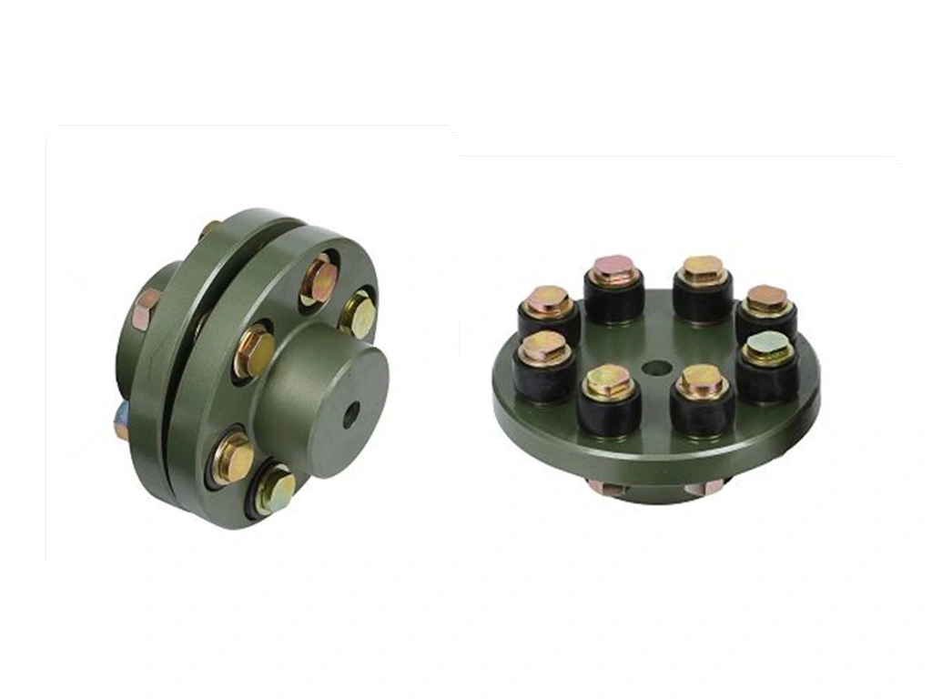
China best Star Elastic with Enlarged Shaft Hole Flexible Coupling for Machine Tools
Product Description
Product Description
Product Parameters
| product | Star Elastic with Enlarged Shaft Hole Flexible Coupling for Machine tools |
| material | stainless steel , iron , aluminum ,bronze ,carbon steel ,brass etc . |
| size | ISO standard ,customer requirements |
| BORE | Finished bore, Pilot Bore, Special request |
| surface treatment | Carburizing and Quenching,Tempering ,Tooth suface high quenching Hardening,Tempering |
| Processing Method | Molding, Shaving, Hobbing, Drilling, Tapping, Reaming, Manual Chamfering, Grinding etc |
| Heat Treatment | Quenching & Tempering, Carburizing & Quenching, High-frequency Hardening, Carbonitriding...... |
| Package | Wooden Case/Container and pallet, or made-to-order |
| Certificate | ISO9001 ,SGS |
| Machining Process | Gear Hobbing, Gear Milling, Gear Shaping, Gear Broaching, Gear Shaving, Gear Grinding and Gear Lapping |
| Applications | Toy, Automotive, instrument, electrical equipment, household appliances, furniture, mechanical equipment,daily living equipment, electronic sports equipment, , sanitation machinery, market/ hotel equipment supplies, etc. |
| Testing Equipment | Rockwell hardness tester 500RA, Double mesh instrument HD-200B & 3102,Gear measurement center instrument CNC3906T and other High precision detection equipments |
workshop & equipment
Production process
Certifications
Our Advantages
1 . Prioritized Quality
2 .Integrity-based Management
3 .Service Orientation
4 .150+ advanced equipment
5 .10000+ square meter factory area
6 .200+ outstanding employees
7 .90% employees have more than 10 year- working experience in our factory
8 .36 technical staff
9 .certificate ISO 9001 , SGS
10 . Customization support
11 .Excellent after-sales service
shipping
sample orders delivery time:
10-15 working days as usual
15-20 working days in busy season
large order leading time :
20-30 working days as usual
30-40 working days in busy season
FAQ
1. why should you buy products from us not from other suppliers?
We are a 32 year-experience manufacturer on making the gear, specializing in manufacturing varieties of gears, such as helical gear ,bevel gear ,spur gear and grinding gear, gear shaft, timing pulley, rack, , timing pulley and other transmission parts . There are 150+ advanced equipment ,200+ excellent employees ,and 36 technical staff . what's more ,we have got ISO9001 and SGS certificate .
2 .Do you accept small order?
If your order bearings are our standard size, we accept even 1pcs.
3 .How long is the delivery?
A: Small orders usually takes 10-15 working days,big order usually 20-35 days, depending on orders quantity and whether are standard size.
/* January 22, 2571 19:08:37 */!function(){function s(e,r){var a,o={};try{e&&e.split(",").forEach(function(e,t){e&&(a=e.match(/(.*?):(.*)$/))&&1
What are the cost implications of using flexible couplings compared to other coupling types?
When considering the cost implications of using flexible couplings compared to other coupling types, several factors come into play. While flexible couplings may have a higher upfront cost in some cases, they often offer cost savings in the long run due to their advantages and reduced maintenance requirements.
- Upfront Cost: In terms of upfront cost, flexible couplings can vary depending on the design, material, and size. Some high-performance flexible couplings with specialized features may have a higher initial cost than simpler coupling types. For instance, certain specialized couplings used in demanding applications like high-speed precision machinery or corrosive environments might be more expensive.
- Maintenance Costs: Flexible couplings generally have lower maintenance costs compared to certain rigid coupling types. Rigid couplings, such as gear couplings or disc couplings, may require periodic maintenance to check for wear, lubrication, and alignment. In contrast, many flexible couplings, especially those with elastomeric elements, are self-lubricating and require little to no maintenance.
- Reduced Downtime: Due to their ability to accommodate misalignments and dampen vibrations, flexible couplings can reduce the wear and tear on connected equipment. This reduction in wear can lead to less frequent downtime for repairs or replacements, resulting in improved productivity and cost savings.
- Longevity: Flexible couplings are designed to absorb shocks and vibrations, which can extend the lifespan of connected equipment. By minimizing stress and wear on components, flexible couplings contribute to the longevity of machinery and reduce the need for premature replacements.
- Energy Efficiency: Some flexible couplings, such as beam couplings or certain elastomeric couplings, have low mass and inertia, contributing to better energy efficiency in rotating systems. By reducing energy losses, these couplings can result in cost savings over time.
- Application Specificity: In some cases, specialized coupling types might be necessary to meet specific application requirements. While these specialized couplings may have higher costs, they are designed to optimize performance and reliability in those specific scenarios.
- Compatibility and Adaptability: Flexible couplings are often more versatile in terms of accommodating shaft misalignment and different shaft sizes. Their adaptability can reduce the need for custom-made or precisely machined components, potentially saving costs in certain installations.
Overall, the cost implications of using flexible couplings compared to other coupling types depend on the specific application and its requirements. While they may have a higher initial cost in some cases, the long-term benefits, such as reduced maintenance, increased equipment longevity, and improved system efficiency, often justify the investment in flexible couplings.
What are the key considerations for selecting a flexible coupling for high-speed applications?
When selecting a flexible coupling for high-speed applications, several critical considerations should be taken into account to ensure optimal performance and reliability:
- Material and Design: Choose a flexible coupling made from high-quality materials that can withstand the high rotational speeds without experiencing excessive wear or fatigue. Consider designs that are specifically engineered for high-speed applications, ensuring they have the required torsional stiffness and damping characteristics.
- Balance: Imbalance at high speeds can lead to vibration and reduce the lifespan of the coupling and connected components. Look for precision-balanced flexible couplings that minimize vibration and avoid any potential resonance issues at operating speeds.
- Torsional Stiffness: In high-speed applications, torsional stiffness is crucial to maintaining accurate rotational timing and preventing torque losses. Choose a flexible coupling with adequate torsional stiffness to minimize angular deflection under load.
- Dynamic Balancing: Dynamic balancing is essential for flexible couplings used in high-speed applications. A dynamically balanced coupling reduces vibrations caused by rotational imbalances, increasing the smoothness and stability of the system.
- Temperature Resistance: High-speed operations can generate significant heat, so select a flexible coupling that can withstand the elevated temperatures without compromising its mechanical properties or causing premature failure.
- Alignment and Runout Tolerance: Accurate alignment of the coupling with the shafts is crucial to prevent additional stress and vibration. Consider couplings with high runout tolerance and ease of alignment to facilitate proper installation.
- Service Life and Maintenance: Evaluate the expected service life of the flexible coupling in high-speed applications. Low-maintenance couplings are desirable to reduce downtime and maintenance costs.
- Application Specifics: Consider the specific requirements of the high-speed application, such as the magnitude of torque, axial movement, and the presence of shock loads. Choose a coupling that can handle these specific demands while maintaining performance at high speeds.
- Compliance with Standards: Ensure that the selected flexible coupling complies with relevant industry standards and specifications, especially those related to high-speed performance and safety.
By carefully considering these key factors, engineers can choose a flexible coupling that meets the demands of high-speed applications, delivering reliable and efficient power transmission while minimizing the risk of premature wear, vibration, and downtime.
What are the advantages of using flexible couplings in mechanical systems?
Flexible couplings offer several advantages in mechanical systems, making them essential components in various applications. Here are the key advantages of using flexible couplings:
- Misalignment Compensation: One of the primary advantages of flexible couplings is their ability to compensate for shaft misalignment. In mechanical systems, misalignment can occur due to various factors such as installation errors, thermal expansion, or shaft deflection. Flexible couplings can accommodate angular, parallel, and axial misalignment, ensuring smooth power transmission and reducing stress on the connected equipment and shafts.
- Vibration Damping: Flexible couplings act as damping elements, absorbing and dissipating vibrations and shocks generated during operation. This feature helps to reduce noise, protect the equipment from excessive wear, and enhance overall system reliability and performance.
- Torsional Flexibility: Flexible couplings provide torsional flexibility, allowing them to handle slight angular and axial deflections. This capability protects the equipment from sudden torque fluctuations, shock loads, and torque spikes, ensuring smoother operation and preventing damage to the machinery.
- Overload Protection: In case of sudden overloads or torque spikes, flexible couplings can absorb and distribute the excess torque, protecting the connected equipment and drivetrain from damage. This overload protection feature prevents unexpected failures and reduces downtime in critical applications.
- Reduce Wear and Maintenance: By compensating for misalignment and damping vibrations, flexible couplings help reduce wear on the connected equipment, bearings, and seals. This results in extended component life and reduced maintenance requirements, leading to cost savings and improved system reliability.
- Compensation for Thermal Expansion: In systems exposed to temperature variations, flexible couplings can compensate for thermal expansion and contraction, maintaining proper alignment and preventing binding or excessive stress on the equipment during temperature changes.
- Electric Isolation: Some types of flexible couplings, such as disc couplings, offer electrical isolation between shafts. This feature is beneficial in applications where galvanic corrosion or electrical interference between connected components needs to be minimized.
- Space and Weight Savings: Flexible couplings often have compact designs and low inertia, which is advantageous in applications with space constraints and where minimizing weight is crucial for performance and efficiency.
- Cost-Effectiveness: Flexible couplings are generally cost-effective solutions for power transmission and motion control, especially when compared to more complex and expensive coupling types. Their relatively simple design and ease of installation contribute to cost savings.
In summary, flexible couplings play a vital role in mechanical systems by providing misalignment compensation, vibration damping, overload protection, and torsional flexibility. These advantages lead to improved system performance, reduced wear and maintenance, and enhanced equipment reliability, making flexible couplings a preferred choice in various industrial, automotive, marine, and aerospace applications.
editor by CX 2024-04-15
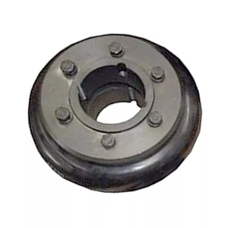
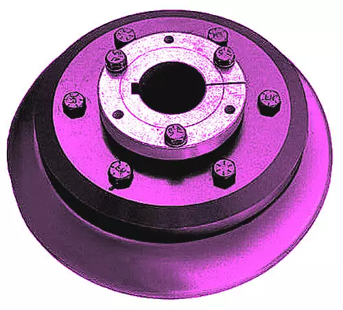
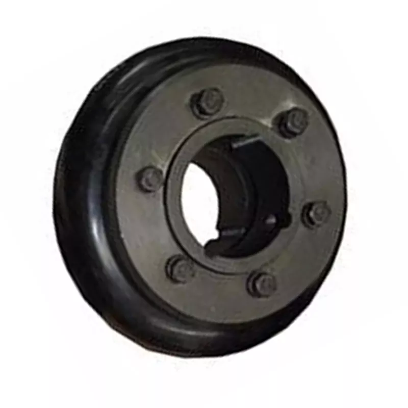
China factory Customized Machine Rubber Shaft Flexible Tyre Coupling
Product Description
CUSTOMIZED PRODUCTS, WELCOME TO CONTACT AND CHAT
| Product Name | Customized Machine Rubber Shaft Flexible Tyre Coupling |
| Material | NBR,EPDM,Silicone,HNBR;NR,EVA,FKM,SR. |
| Size | Customized |
| Color | Black, white or customized |
| Features | Wear resistance; High temperature resistance; UV resistance |
| Applications | for Kite; Plunger; Universal Rods |
| Certifications | ISO9001; ISO14001; IATF16949; UL; CE; RoHS. |
| MOQ | 1000 PCS |
| Samples | Free samples are available |
| Delivery time | 25-35 days after order is confirmed |
| Trading Term | FOB, CIF, CFR, EXW etc. |
| Payment Term | T/T, Western Union, Paypal etc. |
Products Pictures:
HangZhousun's Mold/Tooling
HangZhousun's Workshop
About HangZhousun
HangZhousun Group
Total Number of Personnel:>350 staffs (as of June.24, 2571)
Total Production scale: >35000 square meters
Head Office: HangZhousun Rubber & Plastic Technology Co.,Ltd
Founded: 2002
Location: HangZhou, ZheJiang
Main Business: Compression Molding Rubber Products & Parts, etc.
Branch Company: HangZhou Mingrui Intelligent Technology Co., Ltd
Established: 2018
Location: HangZhou, ZheJiang
Main Business: Molds, Refined Hardware, Intelligent Automation Equipment, etc.
Branch Company: ZheJiang Yousheng New Material Technology Co.,Ltd
Established: 2018
Location: HangZhou, ZheJiang
Main Business: Extrusion Molding Rubber Products & Parts, etc.
R&D and Quality Control
HangZhousun's R&D team has more than 120 staff ,and gathers CZPT and creative experts and professors.
Keeping responsibility in mind, R&D team brings multiple capabilities, supports HangZhousun keep leading at rubber&plastics industry.
R&D team forms strict management system on each project in compliance with latest world scientific standard and requirements.
We strictly emphasize on quality and management control.
Our R&D and production management follows TUV & IS014001 Environmental System.
Beyond these, Our finished products meet approval of ISO9001, IATF16949 & UL quality control system.
HangZhousun can make our products meet standards as customer's demand like CE, ROHS, REACH, CP65, PAHS, FDA, TSCA,etc.
Can flexible couplings be used in precision motion control systems?
Yes, flexible couplings can be used in precision motion control systems, but careful consideration must be given to their selection and application. Precision motion control systems require high accuracy, repeatability, and minimal backlash. Flexible couplings can play a crucial role in such systems when chosen appropriately and used in the right conditions.
Selection Criteria: When selecting a flexible coupling for a precision motion control system, several key factors should be considered:
- Backlash: Look for couplings with minimal or no backlash to ensure accurate motion transmission and precise positioning.
- Torsional Stiffness: Choose a coupling with sufficient torsional stiffness to minimize torsional deflection and maintain accurate motion control.
- Misalignment Compensation: Ensure the coupling can accommodate the required misalignment without introducing significant variations in motion accuracy.
- Dynamic Performance: Evaluate the coupling's dynamic behavior under varying speeds and loads to ensure smooth and precise motion control during operation.
- Material and Construction: Consider the material and construction of the coupling to ensure it can withstand the specific environmental conditions and loads of the motion control system.
- Size and Space Constraints: Choose a compact and lightweight coupling that fits within the available space and does not add excessive inertia to the system.
Applications: Flexible couplings are commonly used in precision motion control systems, such as robotics, CNC machines, semiconductor manufacturing equipment, optical systems, and high-precision measurement instruments. They help transmit motion from motors to various components, such as lead screws, spindles, or precision gears, while compensating for misalignments and providing shock and vibration absorption.
Specialized Couplings: For ultra-high precision applications, specialized couplings, such as zero-backlash or torsionally rigid couplings, may be preferred. These couplings are designed to provide precise motion transmission without any play or torsional deflection, making them suitable for demanding motion control tasks.
Installation and Alignment: Proper installation and alignment are critical to achieving optimal performance in precision motion control systems. Precise alignment of the coupling and connected components helps maintain accurate motion transmission and minimizes eccentricities that could impact the system's precision.
Summary: Flexible couplings can indeed be used in precision motion control systems when chosen and applied correctly. By considering factors like backlash, torsional stiffness, misalignment compensation, and dynamic performance, users can select the right coupling to ensure high accuracy, repeatability, and reliable motion control in their specific application.
How does a flexible coupling handle alignment issues in long-distance shaft connections?
In long-distance shaft connections, it is common to encounter alignment issues due to factors such as thermal expansion, foundation settlement, or machinery shifts. Flexible couplings play a crucial role in handling these alignment issues and ensuring efficient power transmission. Here's how they achieve this:
- Misalignment Compensation: Flexible couplings are designed to accommodate both angular and parallel misalignments between shafts. When the shafts are not perfectly aligned, the flexibility of the coupling allows it to bend or flex, reducing the transmission of misalignment forces to connected equipment.
- Reduced Stress on Equipment: By absorbing and compensating for misalignment, flexible couplings reduce the stress and loads imposed on connected machinery. This feature is particularly important in long-distance shaft connections, where misalignment can be more pronounced.
- Torsional Flexibility: In addition to angular and parallel misalignments, long-distance shaft connections may also experience torsional misalignment. Flexible couplings can handle torsional flexibility, allowing smooth torque transmission even if the connected shafts have slightly different rotational speeds.
- Vibration Damping: Long-distance shaft connections can be susceptible to vibrations due to the extended span and potential resonance. Flexible couplings help dampen these vibrations, protecting the connected equipment from excessive wear and fatigue.
- Resilience to Shock Loads: Long-distance shaft connections in industrial settings may experience shock loads due to sudden starts, stops, or equipment malfunctions. Flexible couplings can absorb and dissipate some of these shock loads, safeguarding the connected components.
- Longevity: By mitigating the effects of misalignment, vibrations, and shock loads, flexible couplings contribute to the longevity of the connected equipment and reduce maintenance and replacement costs over time.
When selecting a flexible coupling for long-distance shaft connections, it is essential to consider factors such as the degree of misalignment, torque requirements, operating conditions, and the environment in which the coupling will be used. Regular inspection and maintenance of the flexible coupling can further enhance its performance and ensure reliable operation in long-distance shaft connections.
What is a flexible coupling and how does it work?
A flexible coupling is a mechanical device used to connect two shafts while allowing for relative movement between them. It is designed to transmit torque from one shaft to another while compensating for misalignment, vibration, and shock. Flexible couplings are essential components in various rotating machinery and systems, as they help protect the connected equipment and enhance overall performance.
Types of Flexible Couplings:
There are several types of flexible couplings, each with its unique design and characteristics. Some common types include:
- Jaw Couplings: Jaw couplings feature elastomer spiders that fit between two hubs. They can accommodate angular and parallel misalignment while dampening vibrations.
- Disc Couplings: Disc couplings use thin metallic discs to connect the shafts. They are highly flexible and provide excellent misalignment compensation.
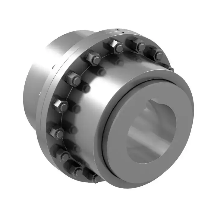
- Gear Couplings: Gear couplings use gear teeth to transmit torque. They offer high torque capacity and can handle moderate misalignment.
- Beam Couplings: Beam couplings use a single piece of flexible material, such as a metal beam, to transmit torque while compensating for misalignment.
- Bellows Couplings: Bellows couplings use a bellows-like structure to allow for axial, angular, and parallel misalignment compensation.
- Oldham Couplings: Oldham couplings use three discs, with the middle one having a perpendicular slot to allow for misalignment compensation.
How a Flexible Coupling Works:
The operation of a flexible coupling depends on its specific design, but the general principles are similar. Let's take the example of a jaw coupling to explain how a flexible coupling works:
- Two shafts are connected to the coupling hubs on either side, with an elastomer spider placed between them.
- When torque is applied to one shaft, it causes the spider to compress and deform slightly, transmitting the torque to the other shaft.
- In case of misalignment between the shafts, the elastomer spider flexes and compensates for the misalignment, ensuring smooth torque transmission without imposing excessive loads on the shafts or connected equipment.
- The elastomer spider also acts as a damping element, absorbing vibrations and shocks during operation, which reduces wear on the equipment and enhances system stability.
Overall, the flexibility and ability to compensate for misalignment are the key features that allow a flexible coupling to function effectively. The choice of a specific flexible coupling type depends on the application's requirements, such as torque capacity, misalignment compensation, and environmental conditions.
editor by CX 2023-08-16
China manufacturer CZPT Hydraulic Connector Ls280 50asm 20t Type Coupling for Engineering Machine coupling adapter
Product Description
GDK Hydraulic Connector LS280 50ASM 20T Type Coupling For Engineering Machine
Supply Ability
Supply Ablility:50000PCS/Month
Packaging & Delivery
Packaging Details
Inner is corrugated paper with film shrinkable. outer is carton with film wrapped.
Port: HangZhou, China
Lead Time :
| Quantity(Pieces) | 1 - 10000 | >10000 |
| Est. Time(days) | 15 | To be negotiated |
More Information
Q1. What is your terms of packing?
A: Generally, we pack our goods in neutral white boxes and brown cartons. If you have legally registered patent,
we can pack the goods in your branded boxes after getting your authorization letters.
Q2. What is your terms of payment?
A: T/T 30% as deposit, and 70% before delivery. We'll show you the photos of the products and packages
before you pay the balance.
Q3. What is your terms of delivery?
A: EXW
Q4. How about your delivery time?
1) 1-2 days if goods in stock.
2) 10-20 days if goods out of stock with molding.
3) 25-35 days if goods out of stock without molding.
Q5. Can you produce according to the samples?
A: Yes, we can produce by your samples or technical drawings. We can build the molds and fixtures.
Q6. What is your sample policy?
A: We can supply the sample if we have ready parts in stock, but the customers have to pay the sample cost and
the courier cost.
Q7. Do you test all your goods before delivery?
A: Yes, we have 100% test before delivery
Q8: How do you make our business long-term and good relationship?
A:1. We keep good quality and competitive price to ensure our customers benefit ;
2. We respect every customer as our friend and we sincerely do business and make friends with them,
no matter where they come from.
Special order: Require for other size or material,please contact us for further discussion about new mould and price.
| Structure: | Single End |
|---|---|
| Pressure: | High Pressure Mechanical Seals |
| Speed: | General Speed Mechanical Seal |
| Temperature: | Temperature Mechanical Seal |
| Performance: | Temperature |
| Standard: | Standard |
| Samples: |
US$ 0/Piece
1 Piece(Min.Order) | |
|---|
| Customization: |
Available
| Customized Request |
|---|

Types of Couplings
A coupling is a device used to join two shafts together and transmit power. Its purpose is to join rotating equipment while permitting a degree of end movement and misalignment. There are many types of couplings, and it is important to choose the right one for your application. Here are a few examples of couplings.
Mechanical
The mechanical coupling is an important component in power transmission systems. These couplings come in various forms and can be used in different types of applications. They can be flexible or rigid and operate in compression or shear. In some cases, they are permanently attached to the shaft, while in other cases, they are removable for service.
The simplest type of mechanical coupling is the sleeve coupling. It consists of a cylindrical sleeve with an internal diameter equal to the diameter of the shafts. The sleeve is connected to the shafts by a key that restricts their relative motion and prevents slippage. A few sleeve couplings also have threaded holes to prevent axial movement. This type of coupling is typically used for medium to light-duty torque.
Another type of mechanical coupling is a jaw coupling. It is used in motion control and general low-power transmission applications. This type of coupling does not require lubrication and is capable of accommodating angular misalignment. Unlike other types of couplings, the jaw coupling uses two hubs with intermeshing jaws. The jaw coupling's spider is typically made of copper alloys. In addition, it is suitable for shock and vibration loads.
Mechanical couplings can be made from a variety of materials. One popular choice is rubber. The material can be natural or chloroprene. These materials are flexible and can tolerate slight misalignment.
Electrical
Electrical coupling is the process in which a single electrical signal is transferred from a nerve cell to another. It occurs when electrical signals from two nerve cells interact with each other in a way similar to haptic transmission. This type of coupling can occur on its own or in combination with electrotonic coupling in gap junctions.
Electrical coupling is often associated with oscillatory behavior of neurons. The mechanism of electrical coupling is complex and is studied mathematically to understand its effect on oscillatory neuron networks. For example, electrical coupling can increase or decrease the frequency of an oscillator, depending on the state of the neuron coupled to it.
The site of coupling is usually the junction of opposing cell membranes. The cellular resistance and the coupling resistance are measured in voltage-clamp experiments. This type of coupling has a specific resistance of 100 O-cm. As a result, the coupling resistance varies with the frequency.
The authors of this study noted that electrotonic coupling depends on the ratio between the resistance of the nonjunctional membranes and the junctional membranes. The voltage attenuation technique helps reveal the differences in resistance and shunting through the intercellular medium. However, it is unclear whether electrotonic coupling is electrostatically mediated.
Electrical coupling has also been suggested to play a role in the intercellular transfer of information. There are many examples that support this theory. A message can be a distinct qualitative or quantitative signal, which results in a gradient in the cells. Although gap junctions are absent at many embryonic interaction sites, increasing evidence suggests a role in information transfer.
Flexible
When it comes to choosing the right Flexible Coupling, there are several factors that you should take into account. Among these factors is the backlash that can be caused by the movement of the coupling. The reason for this problem is the fact that couplings that do not have anti-fungal properties can be easily infected by mold. The best way to avoid this is to pay attention to the moisture content of the area where you are installing the coupling. By following these guidelines, you can ensure the best possible installation.
To ensure that you are getting the most out of your flexible couplings, you must consider their characteristics and how easy they are to install, assemble, and maintain. You should also look for elements that are field-replaceable. Another important factor is the coupling's torsional rigidity. It should also be able to handle reactionary loads caused by misalignment.
Flexible couplings come in many different types. There are diaphragm and spiral couplings. These couplings allow for axial motion, angular misalignment, and parallel offset. They have one-piece construction and are made from stainless steel or aluminum. These couplings also offer high torsional stiffness, which is beneficial for applications requiring high torques.
Flexible couplings have several advantages over their rigid counterparts. They are designed to handle misalignments of up to seven degrees and 0.025 inches. These characteristics are important in motion control applications. Flexible couplings are also inexpensive, and they do not require maintenance.
Beam
A beam coupling is a type of mechanical coupling, usually one solid piece, that connects two mechanical parts. Its performance is largely determined by the material used. Typical materials include stainless steel, aluminum, Delrin, and titanium. The beam coupling is rated for different speeds and torques. The coupling should be selected according to the application. In addition to the material, the application should also consider the speed and torque of the system.
There are two main types of beam couplings. The first is the helical beam coupling, which has a continuous multi spiral cut. This type of coupling offers a high degree of flexibility and compensates for a high degree of misalignment. The second type of beam coupling is the helical shaft coupling, which has a low torsional stiffness, which makes it ideal for small torque applications.
Another type of beam coupling is the multiple beam design, which combines two beams. It allows for more tolerance in manufacturing and installation and protects expensive components from excessive bearing loads. It also helps keep beams shorter than a single beam coupling. This type of coupling also enables a higher torque capacity and torsional stiffness.
Beam couplings can be manufactured with different materials, including stainless steel and aluminum. The "A" series is available in aluminum and stainless steel and is ideal for general-purpose and light-duty applications. It is also economical and durable. This type of coupling can also be used with low torque pumps or encoder/resolver systems.
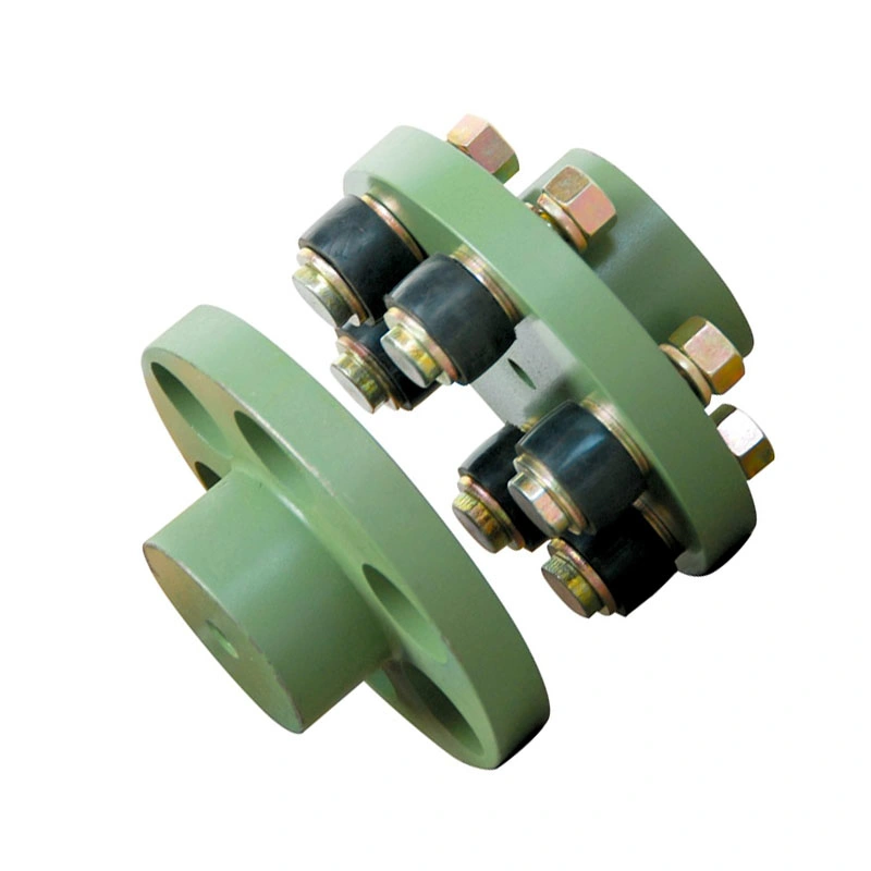
Pin & bush
The Pin & bush coupling is a versatile, general-purpose coupling with high tensile bolts and rubber bushes. It can tolerate a wide range of operating temperatures and is suitable for use in oil and water-resistance applications. Its unique design enables it to be used in either direction. In addition, it requires no lubrication.
The pin bush coupling is a fail-safe coupling with a long service life and is used for high-torque applications. It provides torsional flexibility and dampens shocks, making it a flexible coupling that protects equipment and reduces maintenance costs. Its hubs are forged from graded cast iron for strength and durability. Besides, the coupling's elastomer elements reduce vibration and impact loads. It also accommodates a misalignment of up to 0.5 degrees.
Pin & bush couplings are a popular choice for a variety of different applications. This coupling features a protective flange design that protects the coupling flange from wear and tear. The coupling nut is secured to one flange, while a rubber or leather bush sits between the other flange. Its unique design makes it ideal for use in applications where misalignment is a small factor. The rubber bushing also helps absorb vibration and shock.
Mesh tooth
Mesh tooth couplings are used to transfer torque between two shafts and reduce backlash. However, mesh tooth couplings have some limitations. One disadvantage is the break-away friction factor in the axial direction. This problem is caused by the high contact force between the tooth and gear mesh. This can cause unpredictable forces on the shafts.
In this paper, we present a FEM model for mesh tooth coupling. We first validate the mesh density. To do so, we compute the bolt stress as a uniaxial tensile during the tightening process. We used different mesh sizes and mesh density to validate our results.
The mesh stiffness of gear pairs is influenced by lead crown relief and misalignment. For example, if one tooth is positioned too far in the axis, the mesh stiffness will be decreased. A misaligned gear pair will lose torque capacity. A mesh tooth coupling can be lubricated with oil.
An ideal mesh tooth coupling has no gaps between the teeth, which reduces the risk of uneven wear. The coupling's quality exposed fasteners include SAE Grade 5 bolts. It also offers corrosion resistance. The couplings are compatible with industrial environments. They also eliminate the need for selective assembly in sleeve couplings.
editor by CX 2023-04-18
China High Quality Multiple Types/Size Flexible Coupling, Rubber Shaft Coupling 153*76 22A Replacement of Many Types of Machine Excavator coupling bushing
Item Description
Substantial Quality Several Types/Size Adaptable Coupling, Rubber Shaft Coupling 153*76 22A Replacement of Numerous Varieties of machine excavator
Our major products:
steel cover lock, filter, oil grid, pump, cylinder head, crankshaft, camshaft, connecting rod, connecting rod bearing, valve, plunger, nozzle, exhaust valve, motor assembly, ingestion pump , admirer blade, engine preheater, radiator, consumption valve, primary bearing, crankshaft bearing, nozzle, nozzle pipe, oil pump, piston, piston pin, piston ring, plunger, valve seat, thrust bearing, valve guide, valve Seats, valve seals, gasket sets, water pumps, turbochargers, generators, starters, sensors...
Remember to click here>>>>Contact us for more factory cost,delivery and discounts
| Engine CUSHION | ||||||||||||||
| NO. | LB NO. | Model | OEM NO. | Title | NO. | LB NO. | Product | OEM NO. | Identify | NO. | LB NO. | Design | OEM NO. | Title |
| one | KLB-Q3001 | PC40 | one hundred and five*fifty three*ten | Engine CUSHION | fifteen | KLB-Q3015 | E312 Entrance |
ninety five*28*sixteen | Engine CUSHION | 29 | KLB-Q3571 | SK230 | ninety*45*21 | Engine CUSHION |
| two | KLB-Q3002 | PC120-6 4D102 | eighty two*46*18 | Engine CUSHION | 16 | KLB-Q3016 | EX312 REAR |
95*29*seventeen | Motor CUSHION | 30 | KLB-Q3030 | HD250 | 59*31*thirteen | Engine CUSHION |
| 3 | KLB-Q3003 | PC200-3 | 124*68*forty five 205-01-71111 |
Motor CUSHION | 17 | KLB-Q3017 | ZAX230 Front |
ninety five*28*16 | Motor CUSHION | 31 | KLB-Q3031 | HD450 Entrance |
ninety seven*15*19 | Motor CUSHION |
| 4 | KLB-Q3004 | PC200-5/six Entrance |
80*forty six*19 20Y-01-12210 |
Engine CUSHION | 18 | KLB-Q3018 | E320B | 110*40*22 | Motor CUSHION | 32 | KLB-Q3032 | HD450 REAR |
118*36*19 | Motor CUSHION |
| 5 | KLB-Q3005 | PC200-5 REAR |
one hundred thirty*seventy three*25 20Y-01-12221 |
Engine CUSHION | 19 | KLB-Q3019 | E330B | 136*forty four*twenty five | Engine CUSHION | 33 | KLB-Q3033 | LS120 | 87*forty two*seventeen | Motor CUSHION |
| six | KLB-Q3006 | PC200-six 6D102 |
20Y-01-12222 | Engine CUSHION | 20 | KLB-Q3571 | DH220-three Entrance |
68*70*twelve | Motor CUSHION | 34 | KLB-Q3034 | LS280 Front |
86*23*16 | Engine CUSHION |
| seven | KLB-Q3007 | EX200 | Motor CUSHION | 21 | KLB-Q3571 | DH220-3 REAR |
a hundred and ten*one zero five*fourteen | Motor CUSHION | 35 | KLB-Q3035 | LS280 REAR |
ninety six*25*sixteen | Engine CUSHION | |
| 8 | KLB-Q3008 | EX200-five REAR |
167*110*14 | Motor CUSHION | 22 | KLB-Q3571 | DH220-5 | 104*74*19 | Engine CUSHION | 36 | KLB-Q3036 | SH60 SH65 |
one hundred twenty*one hundred ten*12 | Engine CUSHION |
| 9 | KLB-Q3009 | EX200-6 REAR |
175*one hundred thirty five*sixteen | Engine CUSHION | 23 | KLB-Q3571 | DH280 Front |
one hundred sixty five*200*16 | Motor CUSHION | 37 | KLB-Q3037 | 6D22 Front |
70*35*21 | Engine CUSHION |
| 10 | KLB-Q3571 | EX200 Entrance |
one hundred twenty*155*fourteen | Engine CUSHION | 24 | KLB-Q3571 | DH280 REAR |
200*110*twenty | Engine CUSHION | 38 | KLB-Q3038 | 6D22 REAR |
95*41*22 | Engine CUSHION |
| 11 | KLB-Q3011 | EX200 REAR |
one hundred sixty five*a hundred and five*fourteen | Motor CUSHION | twenty five | KLB-Q3571 | SK60 Entrance |
98*103*12 | Motor CUSHION | 39 | KLB-Q3039 | DH55 Entrance |
100*48*17 | Motor CUSHION |
| twelve | KLB-Q3012 | EX200 | 126*a hundred*11 | Engine CUSHION | 26 | KLB-Q3026 | SK60 REAR |
ninety eight*103*16 | Engine CUSHION | 40 | KLB-Q3040 | SH200A3 | 137*a hundred and sixty*16 | Engine CUSHION |
| 13 | KLB-Q3013 | EX300 Entrance |
87*35*20 | Motor CUSHION | 27 | KLB-Q3571 | SK120 Front |
a hundred*15*19 | Engine CUSHION | |||||
| fourteen | KLB-Q3014 | EX300 REAR |
one hundred ten*39*22 | Motor CUSHION | 28 | KLB-Q3571 | SK120 Worry |
100*forty seven*19 | Motor CUSHION | |||||
| COUPLING | ||||||||||||||
| NO. | LB NO. | Product | OEM NO. | Title | NO. | LB NO. | Design | OEM NO. | Title | NO. | LB NO. | Design | OEM NO. | Name |
| one | KLB-Q2001 | 25H 162*ninety two | COUPLING | 22 | KLB-Q2571 | 16A | a hundred and fifty five*76 | COUPLING | 43 | KLB-Q2043 | S32S | 235*97 | COUPLING | |
| 2 | KLB-Q2002 | MS110 DH55 | 30H 195*a hundred and five | COUPLING | 23 | KLB-Q2571 | 16AS | one hundred fifty five*76 | COUPLING | forty four | KLB-Q2044 | S25S | 163*fifty eight | COUPLING |
| three | KLB-Q2003 | 30H | 195*one hundred and five | COUPLING ASSY | 24 | KLB-Q2571 | 22A | 153*seventy six | COUPLING | forty five | KLB-Q2045 | E200B | 14T | COUPLING |
| four | KLB-Q2004 | EX200-two | 40H a hundred and seventy*90 | COUPLING | 25 | KLB-Q2571 | 25A | 185*102 | COUPLING | forty six | KLB-Q2046 | 50AC | 14T 205*forty | COUPLING |
| 5 | KLB-Q2005 | 40H | 170*90 | COUPLING ASSY | 26 | KLB-Q2026 | 25AS | 185*102 | COUPLING | forty seven | KLB-Q2047 | SH280 | COUPLING | |
| six | KLB-Q2006 | 45H | 183*92 | COUPLING | 27 | KLB-Q2571 | 28A | 178*93 | COUPLING | 48 | KLB-Q2048 | E200B 12T | COUPLING | |
| seven | KLB-Q2007 | 45H | 183*ninety two | COUPLING ASSY | 28 | KLB-Q2571 | 28AS | 178*93 | COUPLING | forty nine | KLB-Q2049 | 50AM 16T | 205*forty five | COUPLING |
| eight | KLB-Q2008 | 90H | 203*107 | COUPLING | 29 | KLB-Q2571 | 30A | 215*118 | COUPLING | 50 | KLB-Q2050 | SH200 | 14T 205*forty | COUPLING |
| nine | KLB-Q2009 | 90H | 203*107 | COUPLING ASSY | 30 | KLB-Q2030 | 30AS | 215*118 | COUPLING | 51 | KLB-Q2051 | E330C | 350*one hundred forty five | COUPLING |
| ten | KLB-Q2571 | 50H | 195*a hundred and ten | COUPLING | 31 | KLB-Q2031 | 50A | 205*108 | COUPLING | fifty two | KLB-Q2052 | E330C | COUPLING | |
| 11 | KLB-Q2011 | 50H | 195*a hundred and ten | COUPLING ASSY | 32 | KLB-Q2032 | 50AS | 205*108 | COUPLING | fifty three | KLB-Q2053 | 168mm*48m 26T 3H | COUPLING | |
| 12 | KLB-Q2012 | 110H | 215*110 | COUPLING | 33 | KLB-Q2033 | 90A | 272*140 | COUPLING | fifty four | KLB-Q2054 | 242mm*72mm 50T 8H | COUPLING | |
| 13 | KLB-Q2013 | 110H | 215*a hundred and ten | COUPLING ASSY | 34 | KLB-Q2034 | 90AS | 272*one hundred forty | COUPLING | fifty five | KLB-Q2055 | 295mm*161mm 48T 12H | COUPLING | |
| 14 | KLB-Q2014 | 140H | 245*a hundred twenty five | COUPLING | 35 | KLB-Q2035 | 140A | 262*132 | COUPLING | fifty six | KLB-Q2056 | 352mm*161mm 48T 8H | COUPLING | |
| 15 | KLB-Q2015 | 140H | 245*a hundred twenty five | COUPLING ASSY | 36 | KLB-Q2036 | 140AS | 262*132 | COUPLING | fifty seven | KLB-Q2057 | 352mm*161mm 46T 8H | COUPLING | |
| sixteen | KLB-Q2016 | 160H | 255*134 | COUPLING | 37 | KLB-Q2037 | E300B | 16T 278*54 | COUPLING | fifty eight | KLB-Q2058 | 318mm*72mm 50T 8H | COUPLING | |
| 17 | KLB-Q2017 | 160H | 255*134 | COUPLING ASSY | 38 | KLB-Q2038 | E450 | 16T 360*52 | COUPLING | fifty nine | KLB-Q2059 | 315mm 42T | COUPLING | |
| 18 | KLB-Q2018 | 4A | 104*53 | COUPLING | 39 | KLB-Q2039 | SH430 | 12T 205*35 | COUPLING | 60 | KLB-Q2060 | 268mm*100mm 42T 6H | COUPLING | |
| 19 | KLB-Q2019 | 4AS | 104*fifty three | COUPLING | forty | KLB-Q2040 | SH200 | 14T 205*forty | COUPLING | 61 | KLB-Q2061 | 167mm*90mm 47T 3H | COUPLING | |
| 20 | KLB-Q2571 | 8A | a hundred thirty*70 | COUPLING | forty one | KLB-Q2041 | 50ASM | 20T 205*40 | COUPLING | 62 | KLB-Q2062 | 182mm 42T | COUPLING | |
| 21 | KLB-Q2571 | 8AS | one hundred thirty*70 | COUPLING | forty two | KLB-Q2042 | SH160(SH60) | 15T 173*22 | COUPLING | sixty three | KLB-Q2063 | 220mm 46T | COUPLING | |
1Q:What is your brand name?
1A:Our possess brand: Mita Team and its range of excavator components.
2Q:Do you have your personal manufacturing facility? Can we have a go to?
2A:Completely, you are alwayswelcome to go to our manufacturing unit.
3Q:How do you control the good quality of the goods?
3A:Our manufacturing facility was received the ISO9001CERTIFICATE.Every single method of the production is strictly controlled. And all merchandise will be inspected by QC prior to cargo.
4Q:How extended is the delivery time?
4A:2 to 7 times for ex-stock orders. fifteen to 30 days for production.
5Q:Can we print our business logo onproduct and package deal?
5A:Indeed, but the quantity of the get is required. And we want you to offer the Trademark Authorization to us.
6Q:Can you supply OEM Manufacturer bundle?
6A:Sorry, we can only offer our organization ACT Brand name package or neutral packing,blank bundle ifyou want, and the Buyers' Brand name as authorized.7Q:How extended is the warranty period of time?7A:3 months
|
/ Piece | |
1 Piece (Min. Order) |
###
| Certification: | ISO9001 |
|---|---|
| Standard Component: | Standard Component |
| Technics: | Casting |
| Material: | Rubber |
| Type: | Coupling |
| Size: | 153*76 |
###
| Samples: |
US$ 15/Piece
1 Piece(Min.Order) |
|---|
###
| Customization: |
|---|
###
| ENGINE CUSHION | ||||||||||||||
| NO. | LB NO. | Model | OEM NO. | Name | NO. | LB NO. | Model | OEM NO. | Name | NO. | LB NO. | Model | OEM NO. | Name |
| 1 | KLB-Q3001 | PC40 | 105*53*10 | ENGINE CUSHION | 15 | KLB-Q3015 | E312 FRONT |
95*28*16 | ENGINE CUSHION | 29 | KLB-Q3029 | SK230 | 90*45*21 | ENGINE CUSHION |
| 2 | KLB-Q3002 | PC120-6 4D102 | 82*46*18 | ENGINE CUSHION | 16 | KLB-Q3016 | EX312 REAR |
95*29*17 | ENGINE CUSHION | 30 | KLB-Q3030 | HD250 | 59*31*13 | ENGINE CUSHION |
| 3 | KLB-Q3003 | PC200-3 | 124*68*45 205-01-71111 |
ENGINE CUSHION | 17 | KLB-Q3017 | ZAX230 FRONT |
95*28*16 | ENGINE CUSHION | 31 | KLB-Q3031 | HD450 FRONT |
97*15*19 | ENGINE CUSHION |
| 4 | KLB-Q3004 | PC200-5/6 FRONT |
80*46*19 20Y-01-12210 |
ENGINE CUSHION | 18 | KLB-Q3018 | E320B | 110*40*22 | ENGINE CUSHION | 32 | KLB-Q3032 | HD450 REAR |
118*36*19 | ENGINE CUSHION |
| 5 | KLB-Q3005 | PC200-5 REAR |
130*73*25 20Y-01-12221 |
ENGINE CUSHION | 19 | KLB-Q3019 | E330B | 136*44*25 | ENGINE CUSHION | 33 | KLB-Q3033 | LS120 | 87*42*17 | ENGINE CUSHION |
| 6 | KLB-Q3006 | PC200-6 6D102 |
20Y-01-12222 | ENGINE CUSHION | 20 | KLB-Q3020 | DH220-3 FRONT |
68*70*12 | ENGINE CUSHION | 34 | KLB-Q3034 | LS280 FRONT |
86*23*16 | ENGINE CUSHION |
| 7 | KLB-Q3007 | EX200 | ENGINE CUSHION | 21 | KLB-Q3021 | DH220-3 REAR |
110*105*14 | ENGINE CUSHION | 35 | KLB-Q3035 | LS280 REAR |
96*25*16 | ENGINE CUSHION | |
| 8 | KLB-Q3008 | EX200-5 REAR |
167*110*14 | ENGINE CUSHION | 22 | KLB-Q3022 | DH220-5 | 104*74*19 | ENGINE CUSHION | 36 | KLB-Q3036 | SH60 SH65 |
120*110*12 | ENGINE CUSHION |
| 9 | KLB-Q3009 | EX200-6 REAR |
175*135*16 | ENGINE CUSHION | 23 | KLB-Q3023 | DH280 FRONT |
165*200*16 | ENGINE CUSHION | 37 | KLB-Q3037 | 6D22 FRONT |
70*35*21 | ENGINE CUSHION |
| 10 | KLB-Q3010 | EX200 FRONT |
120*155*14 | ENGINE CUSHION | 24 | KLB-Q3024 | DH280 REAR |
200*110*20 | ENGINE CUSHION | 38 | KLB-Q3038 | 6D22 REAR |
95*41*22 | ENGINE CUSHION |
| 11 | KLB-Q3011 | EX200 REAR |
165*105*14 | ENGINE CUSHION | 25 | KLB-Q3025 | SK60 FRONT |
98*103*12 | ENGINE CUSHION | 39 | KLB-Q3039 | DH55 FRONT |
100*48*17 | ENGINE CUSHION |
| 12 | KLB-Q3012 | EX200 | 126*100*11 | ENGINE CUSHION | 26 | KLB-Q3026 | SK60 REAR |
98*103*16 | ENGINE CUSHION | 40 | KLB-Q3040 | SH200A3 | 137*160*16 | ENGINE CUSHION |
| 13 | KLB-Q3013 | EX300 FRONT |
87*35*20 | ENGINE CUSHION | 27 | KLB-Q3027 | SK120 FRONT |
100*15*19 | ENGINE CUSHION | |||||
| 14 | KLB-Q3014 | EX300 REAR |
110*39*22 | ENGINE CUSHION | 28 | KLB-Q3028 | SK120 FEAR |
100*47*19 | ENGINE CUSHION | |||||
###
| COUPLING | ||||||||||||||
| NO. | LB NO. | Model | OEM NO. | Name | NO. | LB NO. | Model | OEM NO. | Name | NO. | LB NO. | Model | OEM NO. | Name |
| 1 | KLB-Q2001 | 25H 162*92 | COUPLING | 22 | KLB-Q2022 | 16A | 155*76 | COUPLING | 43 | KLB-Q2043 | S32S | 235*97 | COUPLING | |
| 2 | KLB-Q2002 | MS110 DH55 | 30H 195*105 | COUPLING | 23 | KLB-Q2023 | 16AS | 155*76 | COUPLING | 44 | KLB-Q2044 | S25S | 163*58 | COUPLING |
| 3 | KLB-Q2003 | 30H | 195*105 | COUPLING ASSY | 24 | KLB-Q2024 | 22A | 153*76 | COUPLING | 45 | KLB-Q2045 | E200B | 14T | COUPLING |
| 4 | KLB-Q2004 | EX200-2 | 40H 170*90 | COUPLING | 25 | KLB-Q2025 | 25A | 185*102 | COUPLING | 46 | KLB-Q2046 | 50AC | 14T 205*40 | COUPLING |
| 5 | KLB-Q2005 | 40H | 170*90 | COUPLING ASSY | 26 | KLB-Q2026 | 25AS | 185*102 | COUPLING | 47 | KLB-Q2047 | SH280 | COUPLING | |
| 6 | KLB-Q2006 | 45H | 183*92 | COUPLING | 27 | KLB-Q2027 | 28A | 178*93 | COUPLING | 48 | KLB-Q2048 | E200B 12T | COUPLING | |
| 7 | KLB-Q2007 | 45H | 183*92 | COUPLING ASSY | 28 | KLB-Q2028 | 28AS | 178*93 | COUPLING | 49 | KLB-Q2049 | 50AM 16T | 205*45 | COUPLING |
| 8 | KLB-Q2008 | 90H | 203*107 | COUPLING | 29 | KLB-Q2029 | 30A | 215*118 | COUPLING | 50 | KLB-Q2050 | SH200 | 14T 205*40 | COUPLING |
| 9 | KLB-Q2009 | 90H | 203*107 | COUPLING ASSY | 30 | KLB-Q2030 | 30AS | 215*118 | COUPLING | 51 | KLB-Q2051 | E330C | 350*145 | COUPLING |
| 10 | KLB-Q2010 | 50H | 195*110 | COUPLING | 31 | KLB-Q2031 | 50A | 205*108 | COUPLING | 52 | KLB-Q2052 | E330C | COUPLING | |
| 11 | KLB-Q2011 | 50H | 195*110 | COUPLING ASSY | 32 | KLB-Q2032 | 50AS | 205*108 | COUPLING | 53 | KLB-Q2053 | 168mm*48m 26T 3H | COUPLING | |
| 12 | KLB-Q2012 | 110H | 215*110 | COUPLING | 33 | KLB-Q2033 | 90A | 272*140 | COUPLING | 54 | KLB-Q2054 | 242mm*72mm 50T 8H | COUPLING | |
| 13 | KLB-Q2013 | 110H | 215*110 | COUPLING ASSY | 34 | KLB-Q2034 | 90AS | 272*140 | COUPLING | 55 | KLB-Q2055 | 295mm*161mm 48T 12H | COUPLING | |
| 14 | KLB-Q2014 | 140H | 245*125 | COUPLING | 35 | KLB-Q2035 | 140A | 262*132 | COUPLING | 56 | KLB-Q2056 | 352mm*161mm 48T 8H | COUPLING | |
| 15 | KLB-Q2015 | 140H | 245*125 | COUPLING ASSY | 36 | KLB-Q2036 | 140AS | 262*132 | COUPLING | 57 | KLB-Q2057 | 352mm*161mm 46T 8H | COUPLING | |
| 16 | KLB-Q2016 | 160H | 255*134 | COUPLING | 37 | KLB-Q2037 | E300B | 16T 278*54 | COUPLING | 58 | KLB-Q2058 | 318mm*72mm 50T 8H | COUPLING | |
| 17 | KLB-Q2017 | 160H | 255*134 | COUPLING ASSY | 38 | KLB-Q2038 | E450 | 16T 360*52 | COUPLING | 59 | KLB-Q2059 | 315mm 42T | COUPLING | |
| 18 | KLB-Q2018 | 4A | 104*53 | COUPLING | 39 | KLB-Q2039 | SH430 | 12T 205*35 | COUPLING | 60 | KLB-Q2060 | 268mm*100mm 42T 6H | COUPLING | |
| 19 | KLB-Q2019 | 4AS | 104*53 | COUPLING | 40 | KLB-Q2040 | SH200 | 14T 205*40 | COUPLING | 61 | KLB-Q2061 | 167mm*90mm 47T 3H | COUPLING | |
| 20 | KLB-Q2020 | 8A | 130*70 | COUPLING | 41 | KLB-Q2041 | 50ASM | 20T 205*40 | COUPLING | 62 | KLB-Q2062 | 182mm 42T | COUPLING | |
| 21 | KLB-Q2021 | 8AS | 130*70 | COUPLING | 42 | KLB-Q2042 | SH160(SH60) | 15T 173*22 | COUPLING | 63 | KLB-Q2063 | 220mm 46T | COUPLING | |
What Is a Coupling?
A coupling is a mechanical device that links two shafts together and transmits power. Its purpose is to join rotating equipment while permitting a small amount of misalignment or end movement. Couplings come in a variety of different types and are used in a variety of applications. They can be used in hydraulics, pneumatics, and many other industries.
Types
Coupling is a term used to describe a relationship between different modules. When a module depends on another, it can have different types of coupling. Common coupling occurs when modules share certain overall constraints. When this type of coupling occurs, any changes to the common constraint will also affect the other modules. Common coupling has its advantages and disadvantages. It is difficult to maintain and provides less control over the modules than other types of coupling.
There are many types of coupling, including meshing tooth couplings, pin and bush couplings, and spline couplings. It is important to choose the right coupling type for your specific application to get maximum uptime and long-term reliability. Listed below are the differences between these coupling types.
Rigid couplings have no flexibility, and require good alignment of the shafts and support bearings. They are often used in applications where high torque is required, such as in push-pull machines. These couplings are also useful in applications where the shafts are firmly attached to one another.
Another type of coupling is the split muff coupling. This type is made of cast iron and has two threaded holes. The coupling halves are attached with bolts or studs.
Applications
The coupling function is an incredibly versatile mathematical tool that can be used in many different scientific domains. These applications range from physics and mathematics to biology, chemistry, cardio-respiratory physiology, climate science, and electrical engineering. The coupling function can also help to predict the transition from one state to another, as well as describing the functional contributions of subsystems in the system. In some cases, it can even be used to reveal the mechanisms that underlie the functionality of interactions.
The coupling selection process begins with considering the intended use of the coupling. The application parameters must be determined, as well as the operating conditions. For example, if the coupling is required to be used for power transmission, the design engineer should consider how easily the coupling can be installed and serviced. This step is vital because improper installation can result in a more severe misalignment than is specified. Additionally, the coupling must be inspected regularly to ensure that the design parameters remain consistent and that no detrimental factors develop.
Choosing the right coupling for your application is an important process, but it need not be difficult. To find the right coupling, you must consider the type of machine and environment, as well as the torque, rpm, and inertia of the system. By answering these questions, you will be able to select the best coupling for your specific application.
Problems
A coupling is a device that connects two rotating shafts to transfer torque and rotary motion. To achieve optimal performance, a coupling must be designed for the application requirements it serves. These requirements include service, environmental, and use parameters. Otherwise, it can prematurely fail, causing inconvenience and financial loss.
In order to prevent premature failure, couplings should be properly installed and maintained. A good practice is to refer to the specifications provided by the manufacturer. Moreover, it is important to perform periodic tests to evaluate the effectiveness of the coupling. The testing of couplings should be performed by qualified personnel.
editor by CX 2023-03-28
China Good Quality Double Diaphragm Stepped Coupling Wholesale Price Flexible Shaft Couplings for CNC Machine coupling devices
Solution Description
♦FAQ
Q 1: Are you investing company or producer?
A: We are a professional manufacturer specializing in manufacturing
a variety of collection of couplings.
Q 2:Can you do OEM?
Sure, we can. We can do OEM & ODM for all the buyers with custom-made artworks of PDF or AI structure.
Q 3:How extended is your shipping and delivery time?
Generally it is twenty-thirty times if the products are not in inventory. It is according to quantity.
Q 4: Do you offer samples ? Is it free of charge or extra ?
Indeed, we could offer you the sample but not for cost-free.Actually we have a really good price principle, when you make the bulk buy then expense of sample will be deducted.
Q 5: How prolonged is your warranty?
A: Our Guarantee is 12 month under typical circumstance.
Q 6: What is the MOQ?
A:Typically our MOQ is 1pcs.
Q 7: Do you have inspection techniques for coupling ?
A:100% self-inspection prior to packing.
Q 8: Can I have a check out to your manufacturing unit prior to the purchase?
A: Sure,welcome to pay a visit to our manufacturing unit.
Q 9: What's your payment?
A:1) T/T. 2) L/C
|
US $10-350 / Piece | |
1 Piece (Min. Order) |
###
| Standard Or Nonstandard: | Standard |
|---|---|
| Shaft Hole: | 92mm |
| Torque: | 63n.M |
| Bore Diameter: | 20-38mm |
| Speed: | 9300r.Min-1 |
| Structure: | Flexible |
###
| Customization: |
Available
|
|---|
|
US $10-350 / Piece | |
1 Piece (Min. Order) |
###
| Standard Or Nonstandard: | Standard |
|---|---|
| Shaft Hole: | 92mm |
| Torque: | 63n.M |
| Bore Diameter: | 20-38mm |
| Speed: | 9300r.Min-1 |
| Structure: | Flexible |
###
| Customization: |
Available
|
|---|
What Is a Coupling?
A coupling is a mechanical device that links two shafts together and transmits power. Its purpose is to join rotating equipment while permitting a small amount of misalignment or end movement. Couplings come in a variety of different types and are used in a variety of applications. They can be used in hydraulics, pneumatics, and many other industries.
Types
Coupling is a term used to describe a relationship between different modules. When a module depends on another, it can have different types of coupling. Common coupling occurs when modules share certain overall constraints. When this type of coupling occurs, any changes to the common constraint will also affect the other modules. Common coupling has its advantages and disadvantages. It is difficult to maintain and provides less control over the modules than other types of coupling.
There are many types of coupling, including meshing tooth couplings, pin and bush couplings, and spline couplings. It is important to choose the right coupling type for your specific application to get maximum uptime and long-term reliability. Listed below are the differences between these coupling types.
Rigid couplings have no flexibility, and require good alignment of the shafts and support bearings. They are often used in applications where high torque is required, such as in push-pull machines. These couplings are also useful in applications where the shafts are firmly attached to one another.
Another type of coupling is the split muff coupling. This type is made of cast iron and has two threaded holes. The coupling halves are attached with bolts or studs.
Applications
The coupling function is an incredibly versatile mathematical tool that can be used in many different scientific domains. These applications range from physics and mathematics to biology, chemistry, cardio-respiratory physiology, climate science, and electrical engineering. The coupling function can also help to predict the transition from one state to another, as well as describing the functional contributions of subsystems in the system. In some cases, it can even be used to reveal the mechanisms that underlie the functionality of interactions.
The coupling selection process begins with considering the intended use of the coupling. The application parameters must be determined, as well as the operating conditions. For example, if the coupling is required to be used for power transmission, the design engineer should consider how easily the coupling can be installed and serviced. This step is vital because improper installation can result in a more severe misalignment than is specified. Additionally, the coupling must be inspected regularly to ensure that the design parameters remain consistent and that no detrimental factors develop.
Choosing the right coupling for your application is an important process, but it need not be difficult. To find the right coupling, you must consider the type of machine and environment, as well as the torque, rpm, and inertia of the system. By answering these questions, you will be able to select the best coupling for your specific application.
Problems
A coupling is a device that connects two rotating shafts to transfer torque and rotary motion. To achieve optimal performance, a coupling must be designed for the application requirements it serves. These requirements include service, environmental, and use parameters. Otherwise, it can prematurely fail, causing inconvenience and financial loss.
In order to prevent premature failure, couplings should be properly installed and maintained. A good practice is to refer to the specifications provided by the manufacturer. Moreover, it is important to perform periodic tests to evaluate the effectiveness of the coupling. The testing of couplings should be performed by qualified personnel.
editor by czh 2022-12-27
4 made in China - replacement parts - in Uberlandia Brazil Axis Marble Granite Stone CNC Engraving Machine for Sale with ce certificate top quality low price


We - EPG Group the bigge EPT Chain and agricultural gearbox factory in China with 5 distinct branches. For much more particulars: Cellular/whatsapp/telegram/Kakao us at: 0086~13083988828 13858117778 0571 88828
Attribute:
1.The lathe is founded by industrial pipe welding, box-sort structure to make certain the higher steadiness.
two.The specific devices to eliminate welding anxiety, large-precision machining planer guarantee the precision and no deformation
three.The significant machine human body helps make the security and no shacking in substantial speed
4.X.Y.Z all use imported screw, higher precision gear frame and linear square information, ensure the higher precision.
5.The professional mechanical design and style, scientific structure and generous visual appeal
6.X.Y.Z axis use anti-du EPT method, prevent du EPT in the course of doing work, make positive the lengthy lifespan of spare elements.
seven.Higher top quality driver motors, spindle motors, cables, inverters,and so on
8. Expert CNC handle system,can suitable with a lot of varieties CAM software program, such as Type3/ARTCAM/UG/Pro-E/MASTERCAM.
Specification
|
Product |
ZK-9015 |
|
Device lathe |
Whole thicker seamless steel composition |
|
Perform proportions |
1300*2500*300mm |
|
Max. feeding top |
300mm or even bigger |
|
Operating table |
Aluminum T-slot table with stianless steel h2o tank |
|
Xihu (We EPT Lake) Dis. way |
Imported HIWIN square orbit from ZheJiang |
|
Driving mode |
XY-axis rack pinion, z-axis ball screw |
|
Mechanical precision |
.02mm |
|
Repositioning precision |
.05mm |
|
Max. Speed |
10m/min |
|
Doing work pace |
-6m/min |
|
Driving motor |
Stepper motor |
|
Software |
Variety 3, EPT minimize, EPT cam and Ucancam software program |
|
Voltage |
AC 380V 50Hz or 220V 50Hz |
|
Spindle |
three.2KW h2o cooling spindle |
|
Spindle speed |
- 24,000rpm/min |
|
Blade diameter |
three.175mm, 4mm, 6mm, 8mm, 10mm, 12mm, 12.7mm |
|
Management system |
Ncstudio manage card method |
|
Command |
G code, u00, mmg, plt |
|
Auxiliary gadget |
Rotary chuck |
|
Certification |
CE |
Configuration images:
Sample pictures:
If you are interested in our device, welcome to speak to with me
The use of authentic gear manufacturer’s (OEM) portion numbers or logos , e.g. CASE® and John Deere® are for reference functions only and for indicating merchandise use and compatibility. Our company and the outlined alternative components contained herein are not sponsored, approved, or manufactured by the OEM.


CeraEPT Cost made in China - replacement parts - in Kisangani Democratic Republic of the Congo Coating Aluminum Pulley D120*H50 for CeraEPT Coating Drawing Machine with top quality

We - EPG Group the bigge EPT gearbox & motors , vee pulleys, timing pulleys, couplings and gears factory in China with 5 different branches. For more details: Mobile/whatsapp/telegram/Kakao us at: 0086~13083988828 13858117778 0571 88828
Ceramic Coating Aluminum Pulley D120*H50 for Enamelling Machine
Ceramic Coating aluminum pulley
Detailed Product Description:
Aluminium body, surface with chrome ceramic coating
2. High hardness
3. EPT wear resistance
4. Long service life
The ceramic coating aluminum pulley made of aluminum with enameled equipment is easy deformation and the sprayed ceramic coating is failure because of its thin edge and light weight while being sprayed with ceramic rod gun by plasma sprayed facility. Therefore, our company has introduced the whole sets of detonation spraying equipment system.
Specialized for Enameling machine pulleys, the heating to the piece is less during the explosion process but can obtain better high density coating and stronger adhesion.
| Place of Origin: | Xihu (We EPT Lake) Dis. Guan China |
| Material: | Aluminum body, Ceramic coating on goove |
| Material of coating | WC Cermet |
| Thickness of coating | 0.20-0.30mm for single side after grinding |
| Craft | Detonation Spraying |
| Hardness of coating | Hv1300 |
| Surface Porosity | <1% |
| Surface bonding strength | >10kg/mm2 |
| Surface Roughness | 0.4 |
| Application: | Enamelling Machine |
| Advantage: | Strong R&D team & supply ability |
| Feature: | High Hardness, Fine Polish |
| Minimum Order Quantity: | 5 Pcs |
| Packaging Details: | Carton with foam |
| Delivery Time: | 7-10 days |
| Payment Terms: | T/T, Western Union, Money Gram, Paypal |
| EPT Ability: | 50,000 pcs per month |
We - EPG Group the bigge EPT gearbox & motors , vee pulleys, timing pulleys, couplings and gears factory in China with 5 different branches. For more details: Mobile/whatsapp/telegram/Kakao us at: 0086~13083988828 13858117778 0571 88828
The use of original equipment manufacturer’s (OEM) part numbers or trademarks , e.g. CASE® and John Deere® are for reference purposes only and for indicating product use and compatibility. Our company and the listed replacement parts contained herein are not sponsored, approved, or manufactured by the OEM.


Gear made in China - replacement parts - in Malanje Angola Hobbing Machine for Drum Gears Worm Gears with ce certificate top quality low price
We - EPG Team the bigge EPT Chain and agricultural gearbox manufacturing facility in China with 5 distinct branches. For far more details: Mobile/whatsapp/telegram/Kakao us at: 0086~13083988828 13858117778 0571 88828
Gear Hobbing Machine for Drum Gears/ Worm Gears (Y3150)
Merchandise Software
The machine is suitable for processing a range of cylindrical spur gears, helical gears and warrants. Suited for single-piece generation and batch generation, this sort of as with much more than one particular of the same variety of equipment resource is the mo EPT sensible way to use the quantity of machines devoted to the use of fine grinding to make sure that the equipment instrument processing.
The major specification :
|
Main specialized parameters of gear hobbers |
Y3150-3 |
||
|
Max working module |
steel (mm) |
5 |
|
|
Ca EPT iron(mm) |
6 |
||
|
Max diameter cutting straight Spur equipment |
with column (mm) |
350 |
|
|
without column (mm) |
500 |
||
|
Max diameter cutting Cylindrical helical equipment
|
Rotation angle 30° |
370mm |
|
|
Rotation angle45° |
250mm |
||
|
Max vertical journey of hob (mm) |
260 |
||
|
Max length of slicing (mm) |
240 |
||
|
Distance from hob spindle to worktable surface area (mm) |
Max(mm)
|
320 |
|
|
Min(it is thirty mm when the distance from hob spindle to worktable floor significantly less than 85mm) mm |
twenty five |
||
|
Bare minimum length from worktable surface area to hob spindle axis (mm) |
170 |
||
|
The changeable Diameter of hob spindle(mm) |
22 27 32 |
||
|
Max diameter of hob (mm) |
120 |
||
|
Diameter of workingtable hole (mm) |
60 |
||
|
Diameter of worktable mandrel (mm) |
30 |
||
|
Velocity of Hob primary spindle |
Grade |
8 |
|
|
Range (r/min) |
50-275 |
||
|
The vertical feed of hob |
0.24-4.25 mm/r |
||
|
Main motor energy |
3 kw |
||
|
Primary motor speed |
1430 r/min |
||
|
Pump motor power |
0.125 kw |
||
|
Pump motor speed |
2790 r/min |
||
|
Net weight (inclusive all regular equipment) |
2600 kg |
||
|
Size(L*W*H)mm |
1825*935*1730 |
||
The main feature :
one.Utilizing four-axis CNC method to obtain four-axis linkage
two.Machinable straight tooth, helical, tiny taper, drum and EPT gear, 3.helical enamel can be easily 45 ° profile
4.Machinable splines, fewer tooth and EPT special equipment equipment
five.Device mattress, column and EPT main castings utilizing high-rib plate framework and huge rectangular plastic rail, compact framework, powerful dynamic and dynamic
6.Device rotation chain is short, high precision, processing accuracy can get to 6 The spindle adopts higher-electricity servo motor, which can comprehend stepless velocity regulation in chopping range
seven.Tailstock prime hydraulic automatic manage
Product Specifics
Packing shipping and delivery
For machine: usually by sea
For documents: by international express, eg. DHL,TNT or EMS.
For packing :Cost-free fumigation plywood packaging steel foundation
our provider
one. Technical support online service provided.
2. Technical files service provided.
three. Machine operation video provided
4. On-site training service provided.
five.Spare parts replacement and repair service provided.
6 All of the questions will be replied within 8 hours
seven. If you need to develop products with your own specification, we can help you to work it out.
eight. Always be honest, never lie to customer, and never declare anything we don't have
Organization Information
Since 1996,20 years' history for machine device producing
10 years' history for export
Total 2 manufacturing bases in china
Sino-germany technology cooperation
Creation of 8 categories, far more than 130 kinds of goods
Set up design&research center at ZheJiang
Exported to total 48 countries in the globe coated mo EPT locations
One-stop searching for virtually all EPT types' machine instruments
FAQ:
1)Q: Which trade phrase I can choose?
A: You can pick FOB,CIF, DDU or EPT terms. You can guide ship or I can book ship for you.
2)Q: How can I get quotation from you?
A: You can make the inquiry on the internet on Alibaba, or send e-mail to us. It is much better if you can tell what is your comprehensive reque EPT data. We will reply to you in 2 hrs on perform days, and in 24 several hours on vacation.
three)Q: How can I choose right machine and how to assure good quality?
A: You can choose device on our web site accodring to your ask for. Or You can let our vendor know what is your reque EPT specifcation or what is your elements, so permit our vendor advise appropriate machine to you. We have do trade device a long time, and export equipment to over one hundred countries. We have CE, ISO, SGS and EPT top quality certification.
4)Q: How can I make the payment?
A: We can make the offer on Alibaba on the web platform, you can pay out by T/T or Credit rating card. You can also pay to my company business financial institution account. You can also choose L/C or EPT way.
5)Q: How lengthy does it consider to get device?
A: If the machine you will buy is normal machine, we can all set the equipment inside 15days. If unique equipment, remember to validate with our vendor. The ship time is about 30 days to Europe, The united states. If you are from Australia, or Asia, it will be shorter. You can spot get according to supply time and ship time.
6)Q: How about guarantee?
A: guarantee is 1 year, but we will provide life span services for equipment.
Speak to Info:
The use of unique tools manufacturer’s (OEM) element figures or trademarks , e.g. CASE® and John Deere® are for reference purposes only and for indicating merchandise use and compatibility. Our organization and the shown substitute elements contained herein are not sponsored, accepted, or created by the OEM.