Warranty: 1 12 months, 1 year
Customized support: OBM
Product Amount: LPV70+LMF70
Application: Automotive Market, Biofuel Industry, Industrial Structures, District Energy, Irrigation and Agriculture, Machining, Maritime, Steel and Products Companies, Mining sector, Pharmaceutical industry, temperature manage, Washing and Cleaning, Water Remedy Remedies
Electricity Supply: Hydraulic
Strain: Substantial Stress
Structure: PISTON PUMP, Piston pump-piston pump-gear pump-gear pump
Voltage:
Merchandise name: Corn harvester Hydrostatic transmission Guarantee the substantial trustworthiness
Rotation path: CW, CCW
Sort: Hydraulic Parts
Substance: Cast Iron Cap
Usage: Agriculture equipment
Medium: Hydraulic oil
Function: Hydraulic method factors
Bundle: Plywood situation
Packaging Details: Chian Highaland hydraulic pump for harvester fieldy for wodden box.
Corn harvester Hydrostatic transmission Promise the higher dependability of the solution
·cast iron housing
·hydraulic components
·Application Wheat harvester
·Power components of hydraulic programs
· Custom-made Carbon Steel Straight crown wheel and pinion bevel gear increased effectiveness
·Pressure 35Mpa
·Simple format
·System Answers
·Use Supercharged
·work rapidly
·Fully exchange imported products
·Patent certificate certification
·1 calendar year warranty
Hydrostatic transmission System attributes:
Wheat harvester hydraulic motor pump technique from Highland of China, we can give wheat harvester hydraulic motor pump program with large top quality, large-efficiency parameters. Pump is the variable 1 that is with Cost Pump, and the motor the quantitative, or variable 1 with valve assembly. The handle way of variable displacement pump and motor can be guide or hydraulic operated, and can simply management speed, path and electrical power of the output shaft of hydraulic motor.
Wheat harvester hydraulic motor pump program user shall guarantee that the hydraulic pump utilizes the appropriate formulation of the medium to make sure the cleanliness of the working medium of the gear, and shall not incorporate sound particles.
(Self-cleaning filters are suggested) and use this pump/motor correctly!
Requirements:
Hydrostatic transmission LPV Sequence Specialized parameter
| LPV hydraulic pump and LMF hydraulic motor collection | 30 | 50 | 70 | ninety | 110 | a hundred thirty | ||
| Displacement | Max displacement | ml/r | thirty | 50 | 70 | ninety | a hundred and ten | a hundred thirty |
| Speed | Max steady working pace (Entire load problem) | r/min | 3500 | 3500 | 3200 | 3200 | 2900 | 2900 |
| Rated pace | r/min | 2500 | ||||||
| Min continuous doing work speed | r/min | 500 | ||||||
| Pressure | Rated working stress | Mpa | 35 | |||||
| Max operating pressure (transient) | Mpa | 42 | ||||||
| Continuous functioning force | Mpa | 30 | ||||||
| Allowable shell strain (Complete) | Mpa | Constant0.twenty five, CZPT value0.five | ||||||
| Torque | Steady output torque (Below continuous operating strain) | Nm | 162.three | 252.three | 342.six | 432.9 | 535.3 | 632.four |
| Max output torque | Nm | 227 | 353 | 480 | 606 | 749 | 885 | |
| Power | Ongoing output energy | KW | 45 | 79 | 107 | 139 | 149 | 176 |
| Max electricity | KW | sixty two | 95 | 114 | a hundred and fifty | 173 | 205 | |
| Temperature | Allowable shell temperature | ℃ | 80 | |||||
| Max doing work temperature of oil tank | ℃ | 70 | ||||||
| weight | LPV collection hydraulic pump hydraulic oil drain | kg | forty five | forty six | 63 | 64 | eighty two | 88 |
| LPV series hydraulic motor hydraulic oil drain | kg | thirty | 30 | 36 | 36 | 36 | 38 | |
Hydrostatic transmission safety measures:
Hydraulic oil
The suitable substitute interval for hydraulic oil in a sealed tank system is 2000 hours, and more often if the hydraulic oil is contaminated with water or other exterior resources or subjected to abnormal functioning conditions.
As a standard advice, the 10µ Precision equipment manufacturer standard areas POM gear use resistant nylon plastic equipment inlet oil filter should be replaced every single spring or every 1500 hours (whichever occurs first) on a sealed tank system, or in an open tank method with an air filter fill cap. The oil filter ought to be changed every 500 hrs.
Warmth Exchanger
The warmth exchanger main and fins are retained clean at all times for highest cooling and program performance, and the exterior of the warmth exchanger is checked day-to-day for blockages and cleaned as needed.
Hydrostatic transmission tank:
The wheat harvester hydraulic motor pump syste tank level and the drinking water current in the oil need to be checked day-to-day. If the tank need to be loaded with oil, filtered hydraulic oil have to be used, and all water in the tank must be taken off as essential.
Hydrostatic transmission syste scope:
Mixer truck: concrete mixer truck, cement mixer truck
Coal mining machinery: scraper
Market: pharmaceutical equipment
Transport automobiles: road rollers, concrete pump vans, stabilized soil mixers
FAQ
Q1. Can I have a sample buy for wheat harvester hydraulic motor pump method?
A: Indeed, we welcome sample purchase to test and check high quality.
Q2. What about the lead time?
10 to fifteen times for samples, mass creation in accordance to MOQ
Q3. Do you have any MOQ limit for wheat harvester hydraulic motor pump technique?
A: Minimal MOQ, 1pc for sample checking is available.
Q4. How do you ship the items and how prolonged does it consider to get there?
Ship by sea, it generally normally takes 15-twenty days to get there, and air is also optional.
Q5. How to commence an purchase for wheat harvester hydraulic motor pump method?
A: First of all enable us know your specifications or software.
Next We estimate in accordance to your demands or our suggestions.
Thirdly customer confirms the samples and locations deposit for formal purchase.
Fourthly We organize the production.
Q6: Do you offer you ensure for the goods?
A: Indeed, we offer you 1 a long time warranty to our products.
Q7: How to offer with the defective?
Firstly, our items are created in stringent quality handle program.Secondly, we will inspect the defective pump and motor, and then reply according to the real scenario.
Types of Couplings
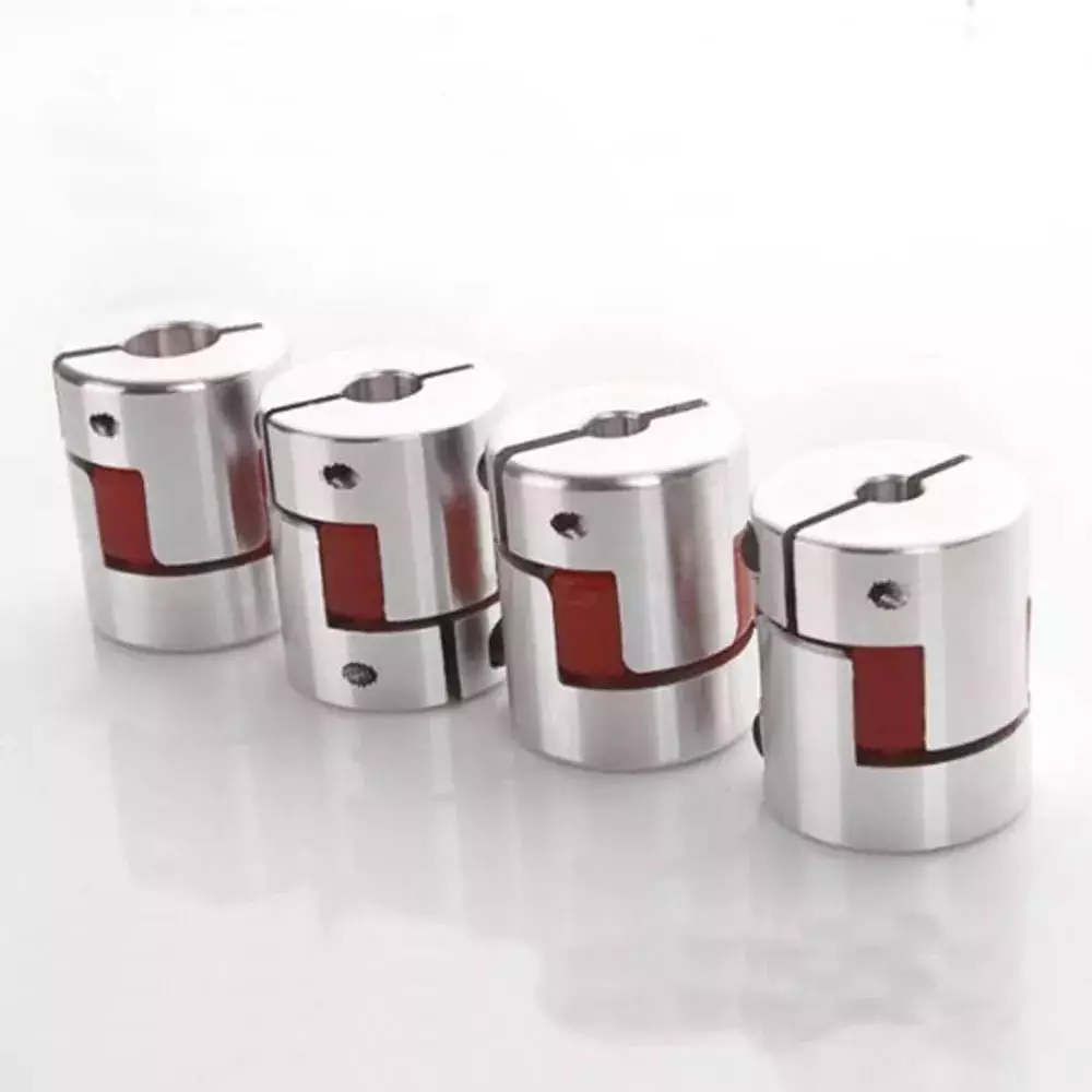
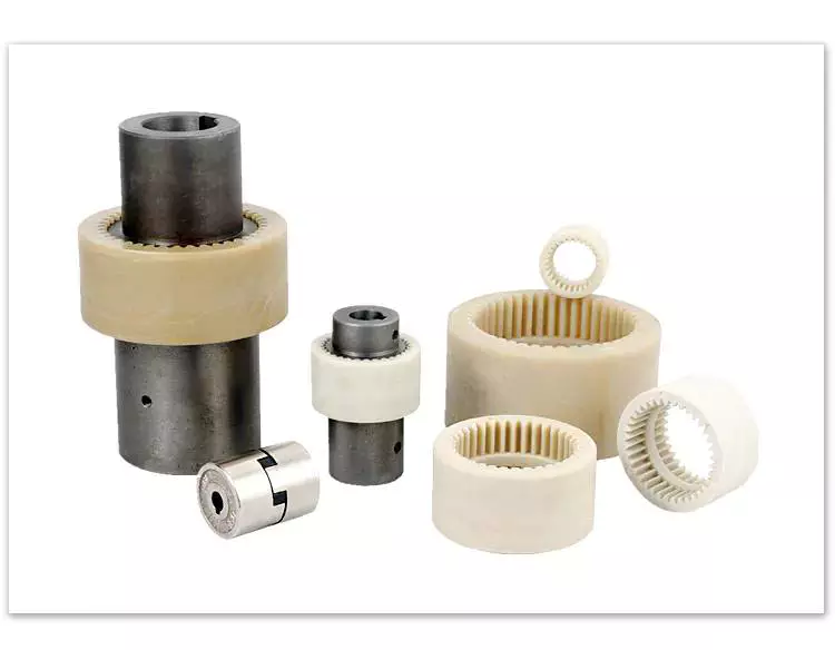
A coupling is a device that connects two shafts and transmits power from one to the other. Its main purpose is to join two pieces of rotating equipment. It also allows for some degree of misalignment or end movement. Here are a few examples of coupling types: Beam coupling, Flexible coupling, Magnetic coupling, and Shaft coupling.
Beam coupling
Beam couplings are used to couple motors and other devices. They are available in several types, including flexible, slit, and rigid beam couplings. Each has unique properties and characteristics. These couplings are best for applications requiring a high level of precision and long life. They are also a practical solution for the connection of stepping and servo motors with screw rods.
Beam couplings are usually made of stainless steel or aluminum alloy, and feature spiral and parallel cut designs. Multiple cuts allow the coupling to accommodate multiple beams and improve angular and parallel misalignment tolerances. Additionally, beam couplings are comparatively cheaper than other types of rotary joints, and they require minimal maintenance.
The materials of a beam coupling should be considered early in the specification process. They are typically made of aluminum or stainless steel, but they can also be manufactured from Delrin, titanium, and other engineering grade materials. Beam couplings are often available in multiple sizes to fit specific shaft diameters.
Beam couplings are a key component of motion control systems. They provide excellent characteristics when used properly, and they are a popular choice for many applications. A thorough understanding of each type of coupling will help to prevent coupling failure and enhance system performance. Therefore, it is important to choose the right coupling for your application.
Various types of beam couplings have unique advantages and disadvantages. The FCR/FSR design has two sets of three beams. It is available in both metric and inch shaft sizes. The FCR/FSR couplings are ideal for light-duty power transmission applications. A metric shaft is more suitable for these applications, while an inch shaft is preferred for heavier duty applications.
Two types of beam couplings are available from Ruland. The Ruland Flexible beam coupling has a multi-helical cut design that offers a greater flexibility than commodity beam couplings. This design allows for higher torque capabilities while minimizing wind-up. In addition, it is also more durable than its commodity counterparts.
Flexible coupling
A flexible coupling is a versatile mechanical connection that allows for the easy coupling of two moving parts. The design of these couplings allows for a variety of stiffness levels and can address a variety of problems, such as torsional vibrations or critical speed. However, there are a number of tradeoffs associated with flexible couplings.
One of the biggest issues is the installation of the coupling, which requires stretching. This problem can be exacerbated by cold temperatures. In such a case, it is vital to install the coupling properly. Using a gear clamp is one of the most important steps in a successful installation. A gear clamp will keep the coupling in place and prevent it from leaking.
Another common type of flexible coupling is the gear coupling. These couplings are composed of two hubs with crowned external gear teeth that mesh with two internally splined flanged sleeves. The massive size of the teeth makes them resemble gears. Gear couplings offer good torque characteristics but require periodic lubrication. These couplings can also be expensive and have a limited number of applications.
Another type of flexible coupling is the SDP/SI helical coupling. These couplings can accommodate axial motion, angular misalignment, and parallel offset. This design incorporates a spiral pattern that makes them flexible. These couplings are available in stainless steel and aluminum.
A flexible coupling has a wide range of applications. Generally, it is used to connect two rotating pieces of equipment. Depending on its design, it can be used to join two pieces of machinery that move in different directions. This type of coupling is a type of elastomeric coupling, which has elastic properties.
There are many types of flexible couplings available for different types of applications. The purpose of a flexible coupling is to transmit rotational power from one shaft to another. It is also useful for transmitting torque. However, it is important to note that not all flexible couplings are created equally. Make sure to use a reputable brand for your coupling needs. It will ensure a reliable connection.
The simplest and most commonly used type of flexible coupling is the grid coupling. This type of coupling uses two hubs with slotted surfaces. The steel grid is allowed to slide along these slots, which gives it the ability to flex. The only limitation of this type of coupling is that it can only tolerate a 1/3 degree misalignment. It can transmit torques up to 3,656 Nm.
Magnetic coupling
Magnetic coupling is a technique used to transfer torque from one shaft to another using a magnetic field. It is the most common type of coupling used in machinery. It is highly effective when transferring torque from a rotating motor to a rotating shaft. Magnetic couplings can handle high torques and high speeds.
Magnetic coupling is described by the energy difference between a high-spin state and a broken symmetry state, with the former being the energy of a true singlet state. In single-determinant theories, this energy difference is called the Kij. Usually, the broken-symmetry state is a state with two interacting local high-spin centers.
The magnetic coupling device is regarded as a qualitative leap in the reaction still industry. It has solved a number of problems that had plagued the industry, including flammability, explosiveness, and leakage. Magnetic couplings are a great solution for many applications. The chemical and pharmaceutical industries use them for various processes, including reaction stills.
Magnetic couplings are a good choice for harsh environments and for tight spaces. Their enclosed design keeps them fluid and dust-proof. They are also corrosion-resistant. In addition, magnetic couplings are more affordable than mechanical couplings, especially in areas where access is restricted. They are also popular for testing and temporary installations.
Another use for magnetic coupling is in touch screens. While touch screens use capacitive and resistive elements, magnetic coupling has found a cool new application in wireless charging. While the finger tracking on touch screens may seem like a boley job, the process is very sensitive. The devices that use wireless charging need to have very large coils that are locked into resonant magnetic coupling.
Magnetic couplings also help reduce hydraulic horsepower. They cushion starts and reduce alignment problems. They can also improve flow in oversized pumps. A magnetic coupling with an 8 percent air gap can reduce hydraulic HP by approximately 27 percent. In addition, they can be used in aggressive environments. They also help reduce repair costs.
Magnetic couplings are a great choice for pumps and propeller systems because they have the added advantage of being watertight and preventing shaft failure. These systems also have the benefit of not requiring rotating seals.
Shaft coupling
A shaft coupling joins two shafts and transmits rotational motion. Generally, shaft couplings allow for some degree of misalignment, but there are also torque limiters. Selecting the right coupling can save you time and money and prevent equipment downtime. Here are the main features to consider when purchasing a coupling for your application.
Shaft couplings should be easy to install and disassemble, transmit full power to the mated shaft, and reduce shock loads. A shaft coupling that does not have projecting parts should be used for machines that move or rotate at high speeds. Some types of shaft couplings are flexible while others are rigid.
Shaft couplings can be used in a variety of applications, including piping systems. They can be used to connect shafts that are misaligned and help maintain alignment. They can also be used for vibration dampening. Shaft couplings also allow shafts to be disconnected when necessary.
Shaft couplings can accommodate a certain amount of backlash, but this backlash must be well within the tolerance set by the system. Extremely high backlash can break the coupling and cause excessive wear and stress. In addition, excessive backlash can lead to erratic alignment readings. To avoid these issues, operators must reduce backlash to less than 2deg.
Shaft couplings are often referred to by different names. Some are referred to as "sliced" couplings while others are known as "slit" couplings. Both types offer high torque and torsional stiffness. These couplings are typically made from metals with various alloys, such as acetal, stainless steel, or titanium.
CZPT Pulley produces shaft couplings for a variety of applications. These products are used in high-power transmission systems. They have several advantages over friction couplings. In addition to minimizing wear, they don't require lubrication. They are also capable of transmitting high torque and high speeds.
Another type of shaft coupling is the universal coupling. It is used to transmit power to multiple machines with different spindles. Its keyed receiving side and flanges allow it to transmit power from one machine to another.

editor by czh 2023-02-16