Tag Archives: elastic coupling

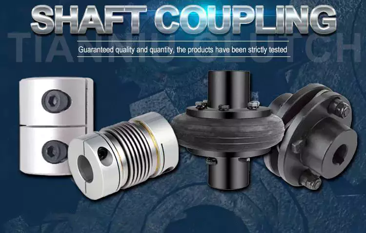
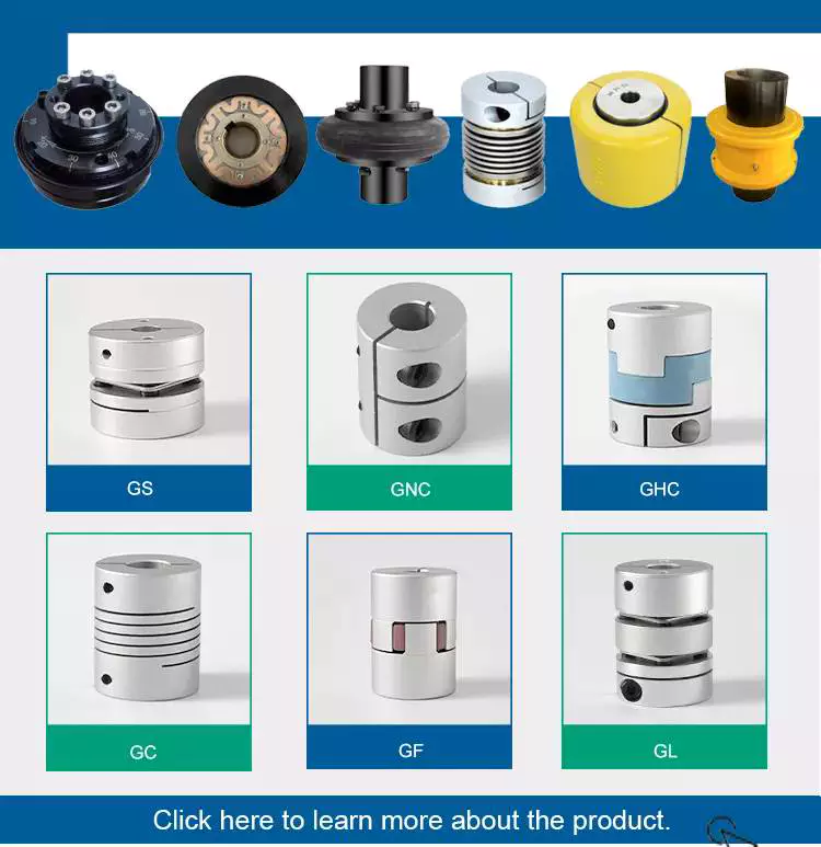
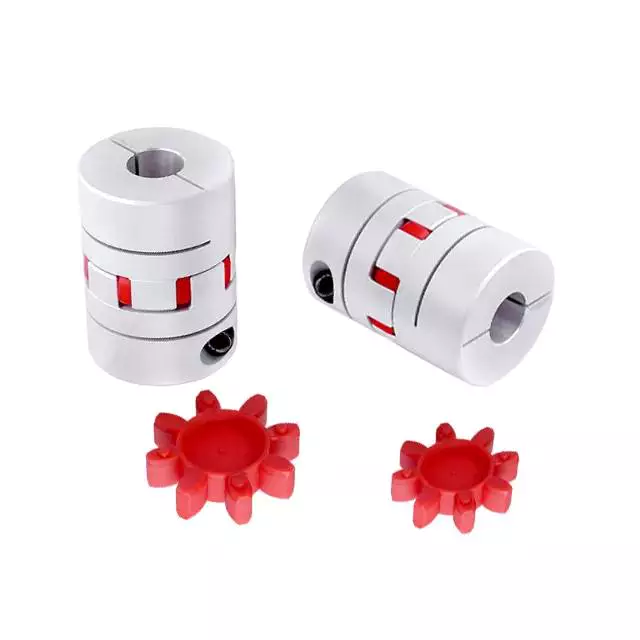
China Elastic coupling A200Flender N-eupex A200 coupling H-type elastomer energy coupling

Guarantee: 3 a long time
Applicable Industries: Garment Outlets, Developing Substance Retailers, Machinery Mend Outlets, Farms, Building works , Vitality & Mining, metallurgy/engineering
Personalized help: OEM, ODM, OBM
Construction: Other
Flexible or Rigid: Flexible
Regular or Nonstandard: Standard
Material: Rubber
Packaging Specifics: cartons
Port: ZheJiang , HangZhou, HangZhou, HangZhou, Hanghzou, HangZhou, HangZhou, ZheJiang , HangZhou, ZheJiang

Specification

itemvalue
Warranty3 years
Applicable IndustriesGarment Stores, Building Materials Outlets, Machinery Mend Retailers, Farms, Design operates , Vitality & Mining, Customized High Good quality La Espresso Equipment Walnut Wood Modification Components Marzocco Barista Equipment Established For La Marzocco GS3 metallurgy/engineering
Customized supportOEM, ODM, OBM
StructureOther
Flexible or RigidFlexible
Standard or NonstandardStandard
MaterialRubber
Brand Namezd
Place of OriginChina
ZheJiang
Packing & Shipping and delivery cartons Firm Profile CZPT Precision Co., Ltd. is positioned in central China. Founded in 1987, it has been focusing on mechanical parts and assembly, advancement and processing of mould areas and pneumatic components. It handles an area of fifty sq. kilometers and has an expense scale of fifty million yuan. FAQ 1. who are we?We are primarily based in ZheJiang , China, begin from 2571,promote to North The us(ten. GBP,CNY,CHFAccepted Payment Type: T/T,L/C,D/P D/A,MoneyGram,Credit Card,PayPal,Western Union,Cash,EscrowLanguage Spoken:English,Chinese,Spanish,Japanese,Portuguese,German,Arabic,French,Russian,Korean,Hindi,Italian

What Is a Coupling?

A coupling is a device that connects two shafts together. It transmits power from one to the other and is used to join rotating equipment. It can also allow for some degree of misalignment and end movement. It is used in mechanical engineering and manufacturing. To learn more about couplings, read this article.
gearboxMechanical connection between two objectsThe present invention relates to a method and assembly for forming a mechanical connection between two objects. The methods of this invention are suitable for connecting both solid and hollow objects. For example, the method can be used to make mechanical connections between two cylinders. This method is particularly useful for connecting two cylinders that are positioned near each other.

Absorbs vibration

A coupling insert is a part of a vehicle's drivetrain that absorbs vibrations. These inserts are designed to prevent couplings from moving out of phase. However, the coupling inserts themselves can wear out and need to be replaced. Universal joints are an alternative if the coupling is out of phase by more than one degree. In addition, internal bearings in the coupling need to be lubricated and replaced when they begin to show signs of wear.
Another embodiment of the invention includes a flexible coupling 25 that includes rearwardly-extending lugs that extend toward the coupling member 23. These lugs interdigitate with corresponding lugs on the coupling member 23. They are spaced circumferentially. A first elastic member 28 is interposed between lugs 26 and 27, and is adapted to yield in a counterclockwise direction. As a result, it absorbs torsional vibrations.
gearbox

Blocks heat transfer

Thermal coupling occurs when a solid block is thermally coupled to the air or fluid passing through it. The amount of heat transferred through a solid block depends on the heat transfer coefficients of the materials. This paper presents a numerical model to understand how heat transfers through different block materials. This work also describes the thermal resistance network for a one-dimensional block.
In some cases, thermal coupling increases the heat transfer mechanism. As illustrated in FIG. 1D, a heatpipe coupler 112 couples two heatpipes 110-1 and 110-2. This configuration allows the pipes to be coupled to the heat source and to the condenser. In addition, the heat pipe couplers may have bellows at the ends to help facilitate linear motion.
Thermal coupling is achieved by ensuring that at least one block is made of a material with a lower thermal expansion coefficient than the annulus. Ideally, the block's mean thermal expansion coefficient is at least twenty percent lower than the annulus's mean thermal expansion coefficient. This ensures that the thermal coupling between the two parts is as efficient as possible.
Another type of thermal coupling is achieved by using flexible elements. These are often washers or springs. These components allow the blocks to maintain physical contact with the post 55, which means that the heat transfer is more efficient even at higher temperatures. The flexibility of these elements also makes it possible to choose an element that will not impede assembly.
gearbox

Protects rotating equipment

A reliable, long-lasting coupling system can reduce the risk of damage to rotating equipment. Designed to protect against torque overload and wear, Voith torque-limiting couplings provide outstanding safety and reliability. As a result, they can deliver maximum performance and minimize equipment downtime. In addition to their long-term benefits, these solutions are ideal for applications where safety and reliability are of paramount importance.
A good coupling provides many advantages, including the ability to transmit power, compensate for axial movement, and absorb shock. It is essential to choose the proper coupling for your application based on the basic conditions of your rotating equipment. For example, if you have two shafts with parallel rotation axes, you should choose a parallel coupling. Otherwise, you should use an angular coupling.
Torque-limiting couplings can also provide protection for rotating equipment by disengaging at a specific torque level. This protects the drive shaft from undergoing catastrophic failure. Torque limiters are particularly helpful for high-value equipment. By preventing catastrophic failure, you can avoid expensive repairs and minimize equipment downtime.
Coupling guards are easy to install and provide effective protection for rotating equipment. These covers are made of sheet metal bent to fit over the shaft. They are durable and easy to remove when necessary. This type of guard can prevent employees from catching their hands, tools, or loose clothing on motor coupling components.
China Elastic coupling A200Flender N-eupex A200 coupling H-type elastomer     energy couplingChina Elastic coupling A200Flender N-eupex A200 coupling H-type elastomer     energy coupling
editor by czh 2023-03-07

China Elastic Rubber Coupling for Air Compressor coupling adapter

Product Description

Rapid Specifics
Place of Origin: ZheJiang , China (Mainland)
Model Identify: Y&F
Product Number: ELASTIC rubber coupling G80HE rubber coupling
Software: Construction machines
Motor Model 1: for Hatz 2L/3L/4L41C 2M/3M/4M41
Engine Design 2: for Hatz W35
Engine Model 3: for Hatz 1D81/1D90 Z788/Z789/Z790
Model: ELASTIC rubber coupling G80HE rubber coupling
Devices: Excavators, bulldozers, Wheel loader flange
Description: Motor Travel Coupling
Material: Rubber, PA6
Coupling assy: Element,

HPV102, 8DC8 8DC9, TierII 522192, sixty, 1,

385, 396, 415, 416,  455, 485,

VIO75, VIO70, 172187-712, 4DNV98


US $200-500
/ Piece
|
1 Piece

(Min. Order)

###

After-sales Service: Online Support
Warranty: 6 Months
Type: Air Compressor Coupling
Application: Excavator
Certification: CE
Condition: New

###

Customization:

###

Packaging Details: ELASTIC rubber coupling G80HE rubber coupling
1. spare parts, with carton package as usual for mini order
2. Main pump, wooden box
3. if need wooden pallets, the customer needs to pay for the wooden pallet charges
JS330LC excavator coupling, hyd. pump coupling for JS330LC
Delivery Detail: 1-7 working days after payment

###

COUPLING "H" SERIES TECHNICAL DATA
                           SIZE  30H 40H 50H 110H 140H 160H
TECHNICAL DATA
DESCRIPTION SYMBOL UNIT 500 600 800 1200 1600 2000
Nominal Torque Tkn Nm
Maximum Torque Tkmax Nm 1400 1600 2000 2500 4000 4000
Maximum Rotational speed Nmax Min-1 4000 4000 4000 4000 3600 3600
COUPLING "A" SERIES TECHNICAL DATA
SIZE 4A/4AS 8A/8AS 16A/16AS 25A/25AS 30A/30AS 50A/50AS 140A/140AS
TECHNICAL DATA
DESCRIPTION SYMBOL UNIT 50 100 200 315 500 700 1700
Nominal Torque Tkn Nm
Maximum Torque Tkmax Nm 125 280 560 875 1400 2100 8750
Maximum Rotational speed Nmax Min-1 7000 6500 6000 5000 4000 4000 3600

Types of Coupling

A coupling is a device used to join two shafts together and transmit power. Its primary function is to join rotating equipment and allows for some end movement and misalignment. This article discusses different types of coupling, including Magnetic coupling and Shaft coupling. This article also includes information on Overload safety mechanical coupling.

Flexible beam coupling

Flexible beam couplings are universal joints that can deal with shafts that are offset or at an angle. They consist of a tube with couplings at both ends and a thin, flexible helix in the middle. This makes them suitable for use in a variety of applications, from motion control in robotics to attaching encoders to shafts.
These couplings are made of one-piece materials and are often made of stainless steel or aluminium alloy. However, they can also be made of acetal or titanium. While titanium and acetal are less common materials, they are still suitable for high-torque applications. For more information about beam couplings, contact CZPT Components.
Flexible beam couplings come in a variety of types and sizes. W series couplings are good for general purpose applications and are relatively economical. Stainless steel versions have increased torque capacity and torsional stiffness. Flexible beam couplings made of aluminum are ideal for servo and reverse motion. They are also available with metric dimensions.
Flexible beam couplings are made of aluminum alloy or stainless steel. Their patented slot pattern provides low bearing load and high torsional rigidity. They have a long operational life. They also require zero maintenance and can handle angular offset. Their advantages outweigh the disadvantages of traditional beam couplings.
gearbox

Magnetic coupling

Magnetic coupling transfers torque from one shaft to another using a magnetic field. These couplings can be used on various types of machinery. These types of transmissions are very useful in many situations, especially when you need to move large amounts of weight. The magnetic field is also very effective at reducing friction between the two shafts, which can be extremely helpful if you're moving heavy items or machinery.
Different magnetic couplings can transmit forces either linearly or rotated. Different magnetic couplings have different topologies and can be made to transmit force in various geometric configurations. Some of these types of couplings are based on different types of materials. For example, a ceramic magnetic material can be used for applications requiring high temperature resistance.
Hybrid couplings are also available. They have a hybrid design, which allows them to operate in either an asynchronous or synchronous mode. Hysterloy is an alloy that is easily magnetized and is used in synchronous couplings. A synchronous magnetic coupling produces a coupled magnetic circuit.
Magnetic coupling is a key factor in many physical processes. In a crystal, molecules exhibit different magnetic properties, depending on their atomic configuration. Consequently, different configurations produce different amounts of magnetic coupling. The type of magnetic coupling a molecule exhibits depends on the exchange parameter Kij. This exchange parameter is calculated by using quantum chemical methods.
Magnetic couplings are most commonly used in fluid transfer pump applications, where the drive shaft is hermetically separated from the fluid. Magnetic couplings also help prevent the transmission of vibration and axial or radial loads through the drive shaft. Moreover, they don't require external power sources, since they use permanent magnets.

Shaft coupling

A shaft coupling is a mechanical device that connects two shafts. The coupling is designed to transmit full power from one shaft to the other, while keeping the shafts in perfect alignment. It should also reduce transmission of shock loads. Ideally, the coupling should be easy to connect and maintain alignment. It should also be free of projecting parts.
The shaft couplings that are used in machines are typically made of two types: universal coupling and CZPT coupling. CZPT couplings are designed to correct for lateral misalignment and are composed of two flanges with tongues and slots. They are usually fitted with pins. The T1 tongue is fitted into flange A, while the T2 tongue fits into flange B.
Another type of shaft coupling is known as a "sliced" coupling. This type of coupling compensates for inevitable shaft misalignments and provides high torque. Machined slits in the coupling's outer shell help it achieve high torsional stiffness and excellent flexibility. The design allows for varying engagement angles, making it ideal for many different applications.
A shaft coupling is an important component of any machine. Proper alignment of the two shafts is vital to avoid machine breakdowns. If the shafts are misaligned, extra force can be placed on other parts of the machine, causing vibration, noise, and damage to the components. A good coupling should be easy to connect and should ensure precise alignment of the shaft. Ideally, it should also have no projecting parts.
Shaft couplings are designed to tolerate a certain amount of backlash, but it must be within a system's threshold. Any angular movement of the shaft beyond this angle is considered excessive backlash. Excessive backlash results in excessive wear, stress, and breakage, and may also cause inaccurate alignment readings. It is therefore imperative to reduce backlash before the shaft alignment process.
gearbox

Overload safety mechanical coupling

Overload safety mechanical couplings are devices that automatically disengage when the torque applied to them exceeds a specified limit. They are an efficient way to protect machinery and reduce the downtime associated with repairing damaged machinery. The advantage of overload couplings is their fast reaction time and ease of installation.
Overload safety mechanical couplings can be used in a wide range of applications. Their automatic coupling mechanisms can be used on any face or edge. In addition, they can be genderless, incorporating both male and female coupling features into a single mechanism. This means that they are both safe and gender-neutral.
Overload safety couplings protect rotating power transmission components from overloads. Overload protection devices are installed on electric motors to cut off power if the current exceeds a certain limit. Likewise, fluid couplings in conveyors are equipped with melting plug elements that allow the fluid to escape when the system becomes too hot. Mechanical force transmission devices, such as shear bolts, are designed with overload protection in mind.
A common design of an overload safety mechanical coupling consists of two or more arms and hubs separated by a plastic spider. Each coupling body has a set torque threshold. Exceeding this threshold may damage the spider or damage the jaws. In addition, the spider tends to dampen vibration and absorb axial extension. This coupling style is nearly backlash free, electrically isolating, and can tolerate very little parallel misalignment.
A mechanical coupling may also be a universal joint or jaw-clutch coupling. Its basic function is to connect the driver and driven shafts, and limits torque transfer. These devices are typically used in heavy-duty industries, such as steel plants and rolling mills. They also work well with industrial conveyor systems.
gearbox

CZPT Pulley

The CZPT Pulley coupling family offers a comprehensive range of couplings for motors of all types. Not only does this range include standard motor couplings, but also servo couplings, which require ultra-precise control. CZPT Pulley couplings are also suitable for engine applications where high shocks and vibrations are encountered.
CZPT Pulley couplings have a "sliced" body structure, which allows for excellent torsional stiffness and strength. They are corrosion-resistant and can withstand high rotational speeds. The couplings' design also ensures accurate shaft rotation while limiting shaft misalignment.
CZPT Pulley has introduced the CPU Pin Type couplings, which are effective at damping vibration and maintain zero backlash. They are also made from aluminum and are capable of absorbing heat. They come with recessed tightening screws. They can handle speeds up to 4,000 RPM, and are RoHS-compliant.
China Elastic Rubber Coupling for Air Compressor     coupling adapterChina Elastic Rubber Coupling for Air Compressor     coupling adapter
editor by czh 2022-11-25

China Factory Direct Sale FCL 1# 2# 3# 4# 5# 6# 8# Rubber Couplings Elastic Spiders Flexible Coupling Rubber Bush breakaway coupling

Guarantee: 3 many years
Applicable Industries: Developing Materials Shops, Production Plant, Machinery Restore Shops, Construction works , Other
Custom-made support: OEM, ODM
Structure: Common
Flexible or Rigid: Flexible
Regular or Nonstandard: Normal
Substance: rubber, rubber,plastic,PU,metallic.and so on
Description: Rubber/PU coupling, shaft couling
Manufacturer: MAST
Samples: valiable
Dimension: all common
OEM/ODM: settle for
Coloration: black , yelloe , pink, blue, green.etc
MOQ: one
Packing: Common
Product: GS, GR,MT,T,NM,GS,FCL,HRC.F,J,L,H.etc
Certification: GS
Port: ZheJiang

Name :FCL 1# 2# 3# 4# 5# 6# 8# Rubber couplings elastic spiders Versatile Coupling Rubber Bush
Model: NM, GS, FCL, HRC. F, J, L, H, etc. NM, GS, FCL, HRC. F, J, L, H, and so on.
Dimensions: Make contact with me for all dimension information.
SAMPLE: Supply Cost-free SAMPLE.
DELIEVERY: Inside 30 Days.

Types of Couplings

A coupling is a device that connects two shafts together. It transmits power from one end to another and is used for joining rotating equipment. A coupling is flexible and can accommodate a certain amount of end movement and misalignment. This allows for more flexibility in applications. Various types of couplings are available, and each one serves a specific purpose.
gearbox

Shaft couplings

There are many types of shaft couplings, and they are used in a wide range of applications. The type you need depends on the torque, speed, and horsepower you need, as well as the size of the shaft and its spatial limitations. You may also need to consider whether the coupling will accommodate misalignment.
Some shaft couplings are flexible, while others are rigid. Flexible couplings can accommodate up to two degrees of misalignment. They are available in different materials, including aluminum, stainless steel, and titanium. They can also be known by different names, depending on the industry. Some couplings can also be used in a single or multiple-shaft application.
The first type of shaft coupling is a rigid coupling, which consists of two parts that fit together tightly around the shafts. These couplings are designed to have more flexibility than sleeved models, and they can be used on fixed shafts as well. The flanged coupling, on the other hand, is designed for heavy loads and is made of two perpendicular flanges. The flanges are large enough to accommodate screws and are generally used with heavy-duty applications.
CZPT shaft couplings are a great choice if you're looking for a shaft coupling that delivers high performance, durability, and low cost. These metal disc-style couplings provide low backlash and high torsional stiffness. Their high misalignment tolerance reduces reaction loads on connected components, which makes them ideal for high-speed precision applications. Available in single and double-disc models, they have torque ratings of up to 2,200 in-lbs. (250N) and are available in fourteen sizes.
When using shaft couplings, it is important to choose the right type for your application. Backlash can cause a shaft coupling to break or become unusable. In order to prevent this from happening, you should replace worn or loose parts, and ensure that the hub and key are evenly positioned with the shaft. If you're using a shaft coupling in a motion-control system, it is important to keep the torque level consistent.

Flexible couplings

Flexible couplings are a type of coupling used to connect two shafts. They are made of rubber or plastic and allow for axial movement of the connected equipment. They do not require lubrication and are resistant to fatigue failure. Flexible couplings are useful for a number of applications. A common type of flexible coupling is the gear coupling, which has gear teeth inside its sleeve. Another type of flexible coupling is the metallic membrane coupling. A metallic membrane coupling is flexible due to flexing metallic discs.
One major disadvantage of flexible couplings is their inability to fit certain types of pipe. This is because most couplings need to be stretched to fit the pipe. This problem is often the result of a change in pipe technology. Traditionally, drain and soil pipe is made of ductile iron or cast iron. Today, most pipes are made of PVC, which has a larger outside diameter than either cast or ductile iron. Because of these changes in pipe technology, many coupling manufacturers have not updated their mold sizing.
Flexible couplings can be either metallic, elastomeric, or a combination of the three. While there are some common characteristics of each type, you should always consider the tradeoffs of each type before choosing one. Generally, the most important considerations when selecting a flexible coupling are torque, misalignment, and ease of assembly and maintenance.
Flexible couplings are used in a wide range of industries. They are useful for connecting two pipes to ensure torque transfer. Although the types available are different, these are the most adaptable couplings in the market. They can withstand movement, vibration, and bending without causing any damage to the piping.
gearbox

Clutch couplings

A clutch coupling connects two rotating shafts by friction. The clutch engages power when the engine is running, disengaging power when the brake is applied. Clutch couplings are used in applications where the speed of a machine is variable or where continuous service is required. The clutch can transmit power, torque, and axial force.
Clutch couplings come in a variety of styles and configurations. Some couplings are flexible, while others are rigid. Flexible couplings are available in a variety of materials, including stainless steel and aluminum. Some couplings also have a non-backlash design, which helps compensate for misalignment.
Clutch couplings may be synchronous or asynchronous. Synchronous couplings engage and disengage automatically when the driven machine exceeds its output speed. These couplings are synchronized by a synchronizing mechanism. When the output speed is exceeded, the synchronizing mechanism initiates the engagement process. The synchronizing mechanism does not engage or disengage when the output speed drops.
High speed clutches are available from a variety of manufacturers. Some manufacturers offer OEM assembly, repair services, and third-party logistics. These manufacturers serve the automotive, chemical, food, and wood industries, as well as the oilfield and material handling industries. Custom clutches can be manufactured for specific applications and can be fitted with additional features, such as precision machined teeth or keyway slots and grooves.
Couplings are available in PCE, C/T, and metric bores. Typically, the size of the input and output shafts will determine which type of coupling is needed. In addition, clutches may be configured for intermediate or high speeds, depending on the required torque.

Clamped couplings

Clamped couplings are commonly used in a variety of industries. They can be used in medical equipment, dental equipment, military equipment, laboratory equipment, and in precision industrial controls. They are available in a wide variety of sizes and keyways. This type of coupling offers a number of advantages, including ease of installation and quick and easy replacement.
A clamp coupling connects two parts by compressing them together. The clamping elements can be formed in a variety of ways, but they all have a gap between their surfaces. This friction squeezes the two parts together, much like pulling two rubber gloves apart. This type of coupling is also useful for joining two hoses or piping units.
Clamped couplings are designed with a single or double clamping shaft. The clamping parts are mounted in two halves and are held together by eight socket head cap screws. They offer high torque capacity and require little installation space. Their high rigidity ensures good positioning accuracy, making them ideal for dynamic drives. In addition, they are wear-free and offer simple radial assembly.
The invention relates to a method and system for clamping pipes to a tank vessel. This invention also relates to a method of loading and unloading tank vessels. The method can be used in oil production platforms and other platforms. A single point mooring method is also used in oil production platforms.
Clamped couplings can also be flexible. They can join two shafts together while allowing a small amount of end movement and misalignment. These couplings may also be used in the assembly of motors and gearboxes.
gearbox

CZPT's coupling

CZPT couplings are designed to be flexible, allowing them to accommodate misaligned shafts and transmit torque in either direction. They are made with three discs, two hubs, and a center that are arranged with grooves and fins. These features allow for two degrees of freedom during assembly, and can accommodate misalignment of up to 5% of the shaft diameter.
CZPT couplings have many uses. For example, they can be used to join two parallel coaxial rotating shafts. Their ability to transmit torque at the same rotation mechanism and speed makes them ideal for applications where electrical currents may be a problem. Because the couplings are not made of metal, they are electrically isolated. Designers should test their couplings during the prototype stage to ensure they are working properly.
The CZPT coupling consists of two hubs with one slot on each. An intermediate disk is located between the two hubs. The discs are used to reduce or prevent wear on other machine parts. CZPT couplings are inexpensive and easy to replace. They also have electrical insulation, which makes them easy to repair or replace.
CZPT couplings are a popular choice for stepper motor-driven positioning stages. The plastic center disc offers electrical isolation and absorbs shocks from frequent start/stops. These couplings are available in through-hub and blind-bore styles and can be installed in many applications.
CZPT couplings also allow for small degrees of shaft misalignment. This allows them to function in systems where shaft access is limited. They are easily removed without tools.
China Factory Direct Sale FCL 1# 2# 3# 4# 5# 6# 8# Rubber Couplings Elastic Spiders Flexible Coupling Rubber Bush     breakaway couplingChina Factory Direct Sale FCL 1# 2# 3# 4# 5# 6# 8# Rubber Couplings Elastic Spiders Flexible Coupling Rubber Bush     breakaway coupling
editor by czh

China high quality China FCL Elastic Sleeve Pin Coupling Flexible Shaft Coupling custom coupling coupling half

Guarantee: 1 years
Applicable Industries: Producing Plant, Machinery Fix Retailers, Food & Beverage Manufacturing unit, Design works , Energy & Mining
Tailored help: OEM, ODM, OBM
Composition: Jaw / Spider
Adaptable or Rigid: Flexible
Standard or Nonstandard: Common
Substance: cast 250
Solution name: FCL Adaptable Coupling
Body Material: Solid Iron HT250 + Rubber
Bore kind: Straight Bore
Packaging Details: Generally we pack goods according to customers’ prerequisite. For reference: cartonbox, plastic bag, wood scenario.
Port: ZheJiang

Recommend Goods Why Pick Us Business Profile FAQ Q: Settle for customization?A: Acknowledge. Q: How lengthy is your supply time?A: It is dependent on the item situation. Q: What collection of items do you largely produce?A: Pulleys, couplings, cardan shafts. Q: What is your way of packing?A: Generally we pack items in accordance to customers' necessity. For reference: cartonbox, plastic bag, wood situation.

What Is a Worm Gear Reducer?

If you have never seen a worm gear reducer before, you're missing out! Learn more about these incredible gears and their applications by reading this article! In addition to worm gear reducers, learn about worms and how they're made. You'll also discover what types of machines can benefit from worm gears, such as rock crushers and elevators. The following information will help you understand what a worm gear reducer is and how to find one in your area.
worm shaft

Typical worm shaft

A typical worm has two shafts, one for advancing and one for receding, which form the axial pitch of the gear. Usually, there are eight standard axial pitches, which establish a basic dimension for worm production and inspection. The axial pitch of the worm equals the circular pitch of the gear in the central plane and the master lead cam's radial pitch. A single set of change gears and one master lead cam are used to produce each size of worm.
Worm gear is commonly used to manufacture a worm shaft. It is a reliable and efficient gear reduction system that does not move when the power is removed. Typical worm gears come in standard sizes as well as assisted systems. Manufacturers can be found online. Listed below are some common materials for worm gears. There are also many options for lubrication. The worm gear is typically made from case hardened steel or bronze. Non-metallic materials are also used in light-duty applications.
A self-locking worm gear prevents the worm from moving backwards. Typical worm gears are generally self-locking when the lead angle is less than 11 degrees. However, this feature can be detrimental to systems that require reverse sensitivity. If the lead angle is less than four degrees, back-driving is unlikely. However, if fail-safe protection is a prerequisite, back-driving worm gears must have a positive brake to avoid reverse movement.
Worm gears are often used in transmission applications. They are a more efficient way to reduce the speed of a machine compared to conventional gear sets. Their reduced speed is possible thanks to their low ratio and few components. Unlike conventional gear sets, worm gears require less maintenance and lower mechanical failure than a conventional gear set. While they require fewer parts, worm gears are also more durable than conventional gear sets.
There are two types of worm tooth forms. Convex and involute helicoids have different types of teeth. The former uses a straight line to intersect the involute worm generating line. The latter, on the other hand, uses a trapezoid based on the central cross section of the root. Both of these tooth forms are used in the production of worms. And they have various variations in pitch diameter.
worm shaft

Types of worms

Worms have several forms of tooth. For convenience in production, a trapezoid-based tooth form is used. Other forms include an involute helicoidal or a convolute worm generating a line. The following is a description of each type. All types are similar, and some may be preferred over others. Listed below are the three most common worm shaft types. Each type has its own advantages and disadvantages.
Discrete versus parallel axis: The design of a worm gear determines its ratio of torque. It's a combination of two different metals - one for the worm and one for the wheel - which helps it absorb shock loads. Construction equipment and off-road vehicles typically require varying torques to maneuver over different terrain. A worm gear system can help them maneuver over uneven terrain without causing excessive wear.
Worm gear units have the highest ratio. The sliding action of the worm shaft results in a high self-locking torque. Depending on the angle of inclination and friction, a worm gear can reach up to 100:1! Worm gears can be made of different materials depending on their inclination and friction angle. Worm gears are also useful for gear reduction applications, such as lubrication or grinding. However, you should consider that heavier gears tend to be harder to reverse than lighter ones.
Metal alloy: Stainless steel, brass, and aluminum bronze are common materials for worm gears. All three types have unique advantages. A bronze worm gear is typically composed of a combination of copper, zinc, and tin. A bronze shaft is more corrosive than a brass one, but it is a durable and corrosion-resistant option. Metal alloys: These materials are used for both the worm wheel.
The efficiency of worm gears depends on the assembly conditions and the lubricant. A 30:1 ratio reduces the efficiency to 81:1%. A worm gear is more efficient at higher ratios than an helical gear, but a 30:1 ratio reduces the efficiency to 81%. A helical gear reduces speed while preserving torque to around 15% of the original speed. The difference in efficiency between worm gear and helical gear is about half an hour!

Methods of manufacturing worm shafts

Several methods of manufacturing worm shafts are available in the market. Single-pointed lathe tools or end mills are the most popular methods for manufacturing worms. These tools are capable of producing worms with different pressure angles depending on their diameter, the depth of thread, and the grinding wheel's diameter. The diagram below shows how different pressure angles influence the profile of worms manufactured using different cutting tools.
The method for making worm shafts involves the process of establishing the proper outer diameter of a common worm shaft blank. This may include considering the number of reduction ratios in a family, the distance between the worm shaft and the gear set center, as well as the torques involved. These processes are also referred to as 'thread assembly'. Each process can be further refined if the desired axial pitch can be achieved.
The axial pitch of a worm must match the circular pitch of the larger gear. This is called the pitch. The pitch diameter and axial pitch must be equal. Worms can be left-handed or right-handed. The lead, which refers to the distance a point on the thread travels during one revolution of the worm, is defined by its angle of tangent to the helix on the pitch of the cylinder.
Worm shafts are commonly manufactured using a worm gear. Worm gears can be used in different applications because they offer fine adjustment and high gear reduction. They can be made in both standard sizes and assisted systems. Worm shaft manufacturers can be found online. Alternatively, you can contact a manufacturer directly to get your worm gears manufactured. The process will take only a few minutes. If you are looking for a manufacturer of worm gears, you can browse a directory.
Worm gears are made with hardened metal. The worm wheel and gear are yellow in color. A compounded oil with rust and oxidation inhibitors is also used to make worm gears. These oils adhere to the shaft walls and make a protective barrier between the surfaces. If the compounded oil is applied correctly, the worm gear will reduce the noise in a motor, resulting in a smoother performance.
worm shaft

applications for worm gear reducers

Worm gears are widely used in power transmission applications, providing a compact, high reduction, low-speed drive. To determine the torque ratio of worm gears, a numerical model was developed that makes use of the equation of displacement compatibility and the influence coefficient method, which provides fast computing. The numerical model also incorporates bending deflections of the gear surfaces and the mating surfaces. It is based on the Boussinesq theory, which calculates local contact deformations.
Worm gears can be designed to be right or left-handed, and the worm can turn either clockwise or counter-clockwise. An internal helical gear requires the same hand to operate both parts. In contrast, an external helical gear must be operated by the opposite hand. The same principle applies to worm gears in other applications. The torque and power transferred can be large, but worm gears are able to cope with large reductions in both directions.
Worm gears are extremely useful in industrial machinery designs. They reduce noise levels, save space, and give machines extra precision and fast-stopping capabilities. Worm gears are also available in compact versions, making them ideal for hoisting applications. This type of gear reducer is used in industrial settings where space is an issue. Its smaller size and less noise makes it ideal for applications that need the machine to stop quickly.
A double-throated worm gear offers the highest load capacity while still remaining compact. The double-throated version features concave teeth on both worm and gear, doubling the contact area between them. Worm gears are also useful for low to moderate-horsepower applications, and their high ratios, high output torque, and significant speed reduction make them a desirable choice for many applications. Worm gears are also quieter than other types of gears, reducing the noise and vibrations that they cause.
Worm gears have numerous advantages over other types of gears. They have high levels of conformity and can be classified as a screw pair within a lower-pair gear family. Worm gears are also known to have a high degree of relative sliding. Worm gears are often made of hardened steel or phosphor-bronze, which provides good surface finish and rigid positioning. Worm gears are lubricated with special lubricants that contain surface-active additives. Worm gear lubrication is a mixed lubrication process and causes mild wear and tear.

China high quality China FCL Elastic Sleeve Pin Coupling Flexible Shaft Coupling custom coupling     coupling halfChina high quality China FCL Elastic Sleeve Pin Coupling Flexible Shaft Coupling custom coupling     coupling half
editor by czh